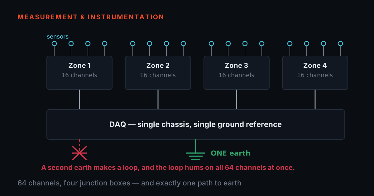
Junction Box Family — BNC Patch Panels, JB04T to JB80T
Nine channel counts, one BNC routing platform — bench panels through a tender-grade 64-channel zoned chassis.
TIERA's junction-box family routes accelerometer and microphone arrays through numbered BNC patch panels, from a 4-channel bench box to an 80-channel floor unit. Every model shares one electrical specification — ±0.1 dB flatness from 10 Hz to 20 kHz is the number that defines the family. The 64-channel configuration adds zoned grouping, a hinged lockable lid and a castor stand, built to a customer tender spec reproduced in full on its model page.

- •Nine channel counts — JB04T, JB08T, JB12T, JB16T, JB24T, JB48T, JB60T, JB64T, JB80T
- •±0.1 dB flatness, 10 Hz–20 kHz, across every model in the family
- •BNC female-to-female panel-mount connectors, one per channel
- •Screw-fixed cover standard; hinged, lockable, zoned chassis build available from 48 channels
- •64-channel configuration built to a customer tender: 4 zones × 16, castor stand, dual-face marking
- •Delivery test report: calibrated analyser, worst-case values, dBV and %
- •Aircraft structure, modal, acoustic-array and SHM applications; 12-month warranty
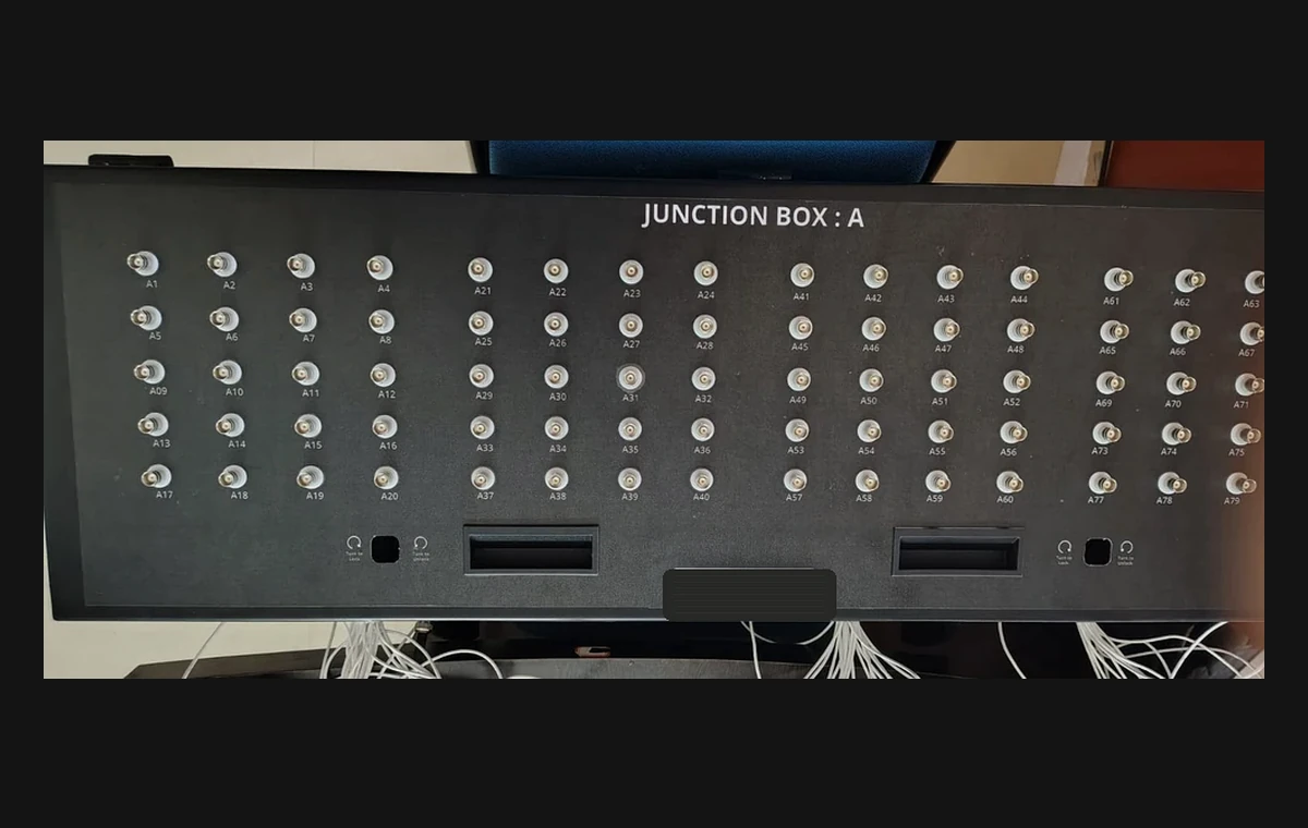
Clean front-panel routing
Numbered BNC channels keep custom high-channel sensor layouts readable during setup, teardown and repeat tests.
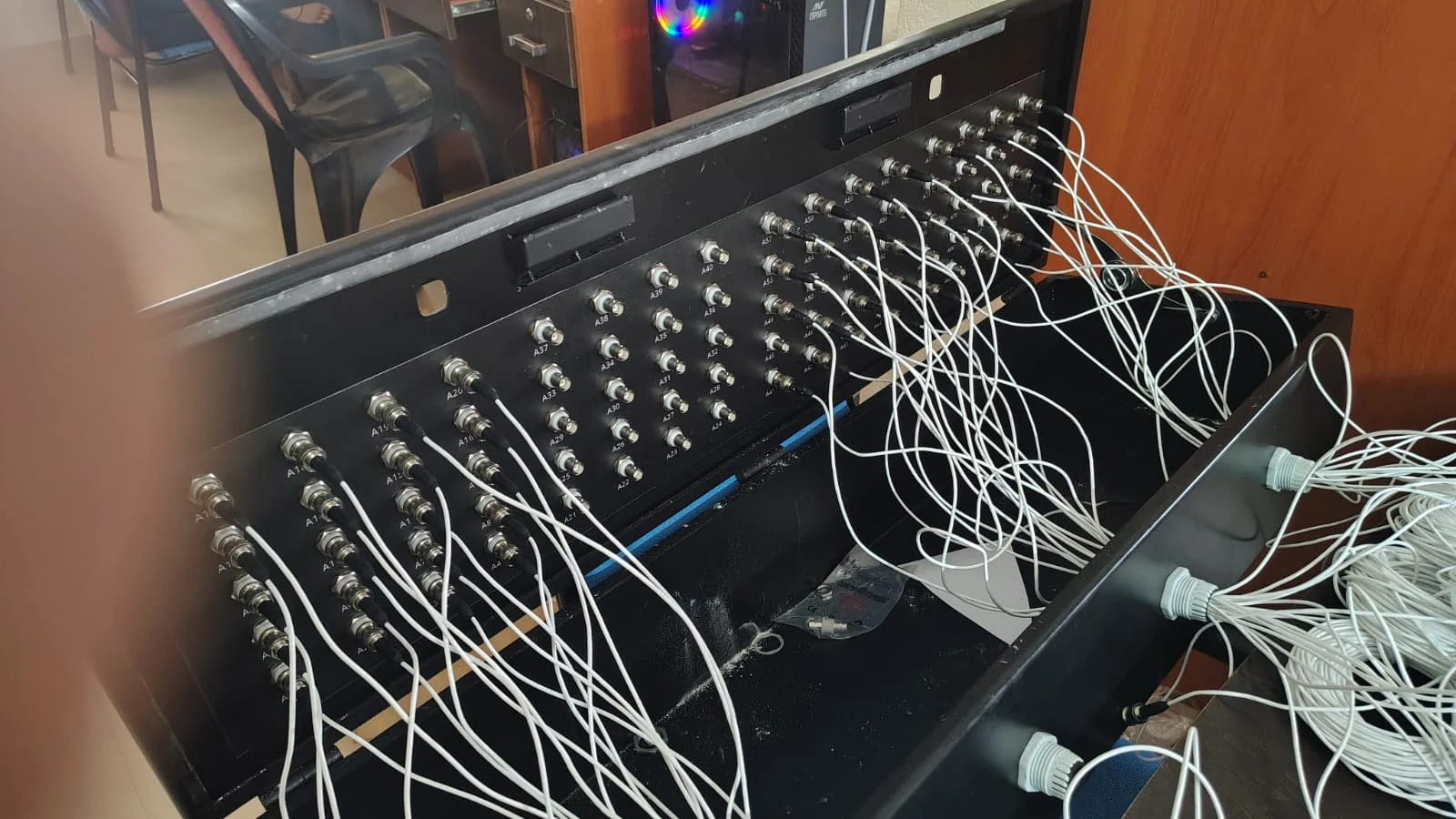
Wired experimental setup
Long cable runs stay organized when accelerometers, microphones and DAQ channels are distributed across a structure.
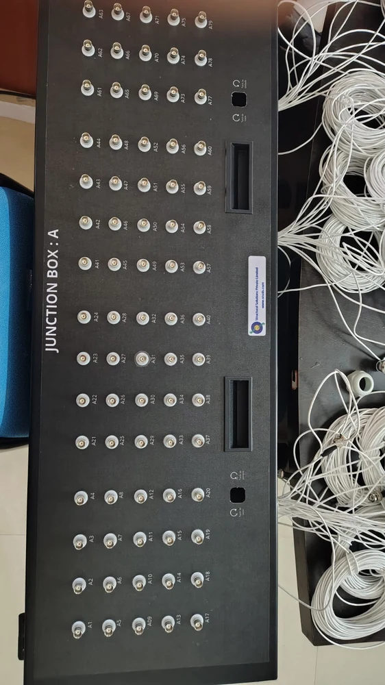
Zone-based channel grouping
Grouped channels make it easier to map sensor zones to DAQ inputs for aircraft, acoustic and SHM workflows.
Choose by channel count and sensor map.
Start with the number of accelerometers or microphones, then group the channels by structure zone, DAQ input and cable-access direction.
Channel count
64, 80 or custom N-channel BNC routing
Zone map
Group sensors by structure, fixture or test area
DAQ handoff
Keep numbering consistent from sensor to report
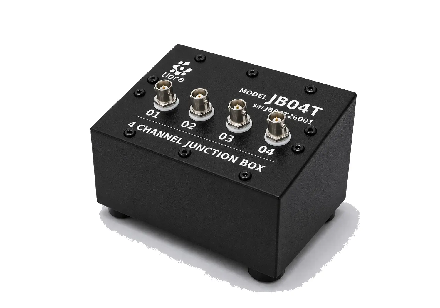
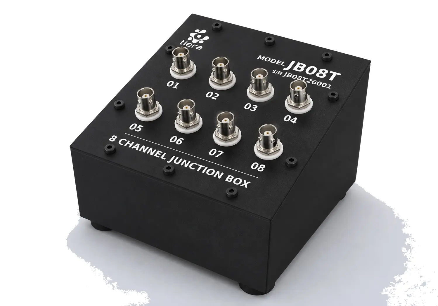
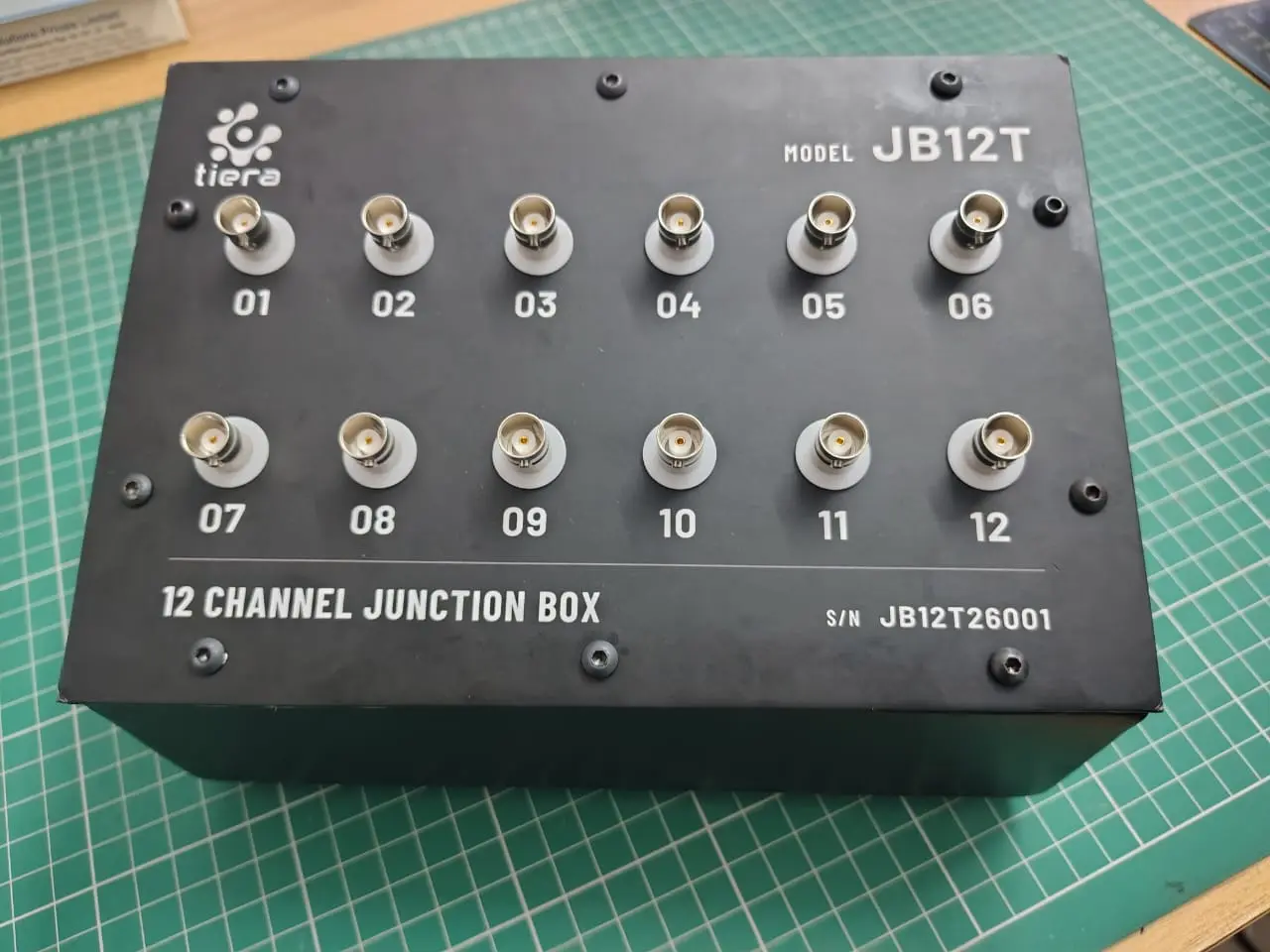
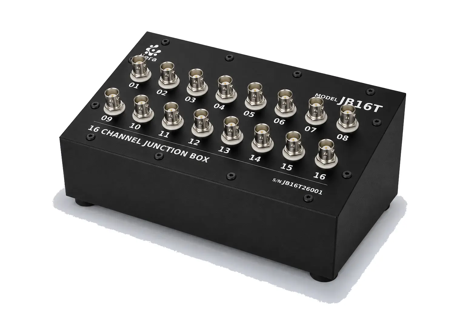
Nine channel counts, two build options
Every unit in the family routes one BNC bulkhead connector per channel through a numbered, silk-screened panel — the same convention on the smallest bench box and the largest floor unit. The difference between models is channel count and, above roughly 32 channels, whether the panel is worth dividing into zones.
| Model | Channels | Panel layout | Confirmed from |
|---|---|---|---|
| JB04T | 4 | 1 row × 4 | Studio render |
| JB08T | 8 | 2 rows × 4 | Studio render |
| JB12T | 12 | 2 rows × 6 | Real bench photograph (6 angles) |
| JB16T | 16 | 2 rows × 8 | Studio render |
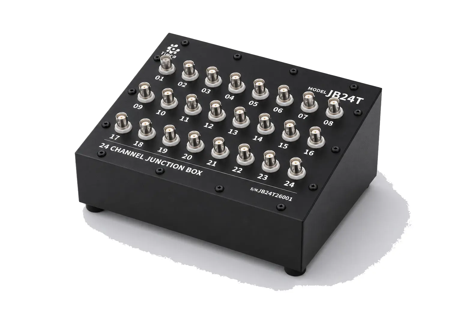
| JB24T | 24 | 3 rows × 8 | Studio render |
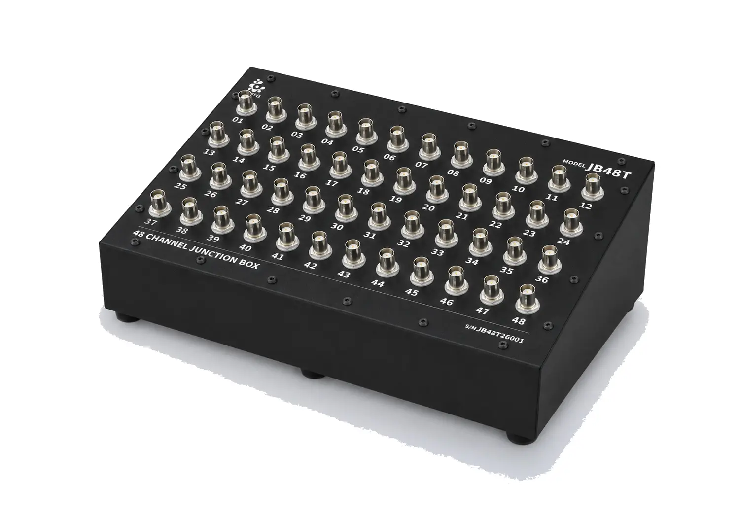
| JB48T | 48 | 4 rows × 12 | Studio render |
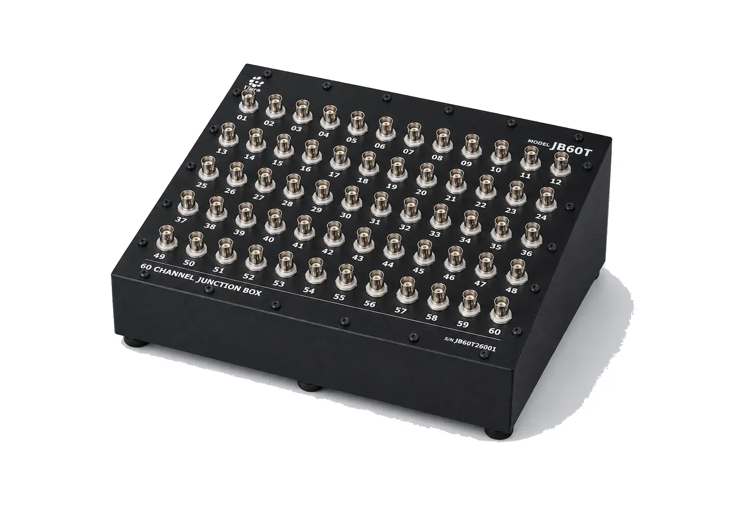
| JB60T | 60 | 5 rows × 12 | Studio render |
| JB64T | 64 | 4 zones × 16 | Customer tender specification |
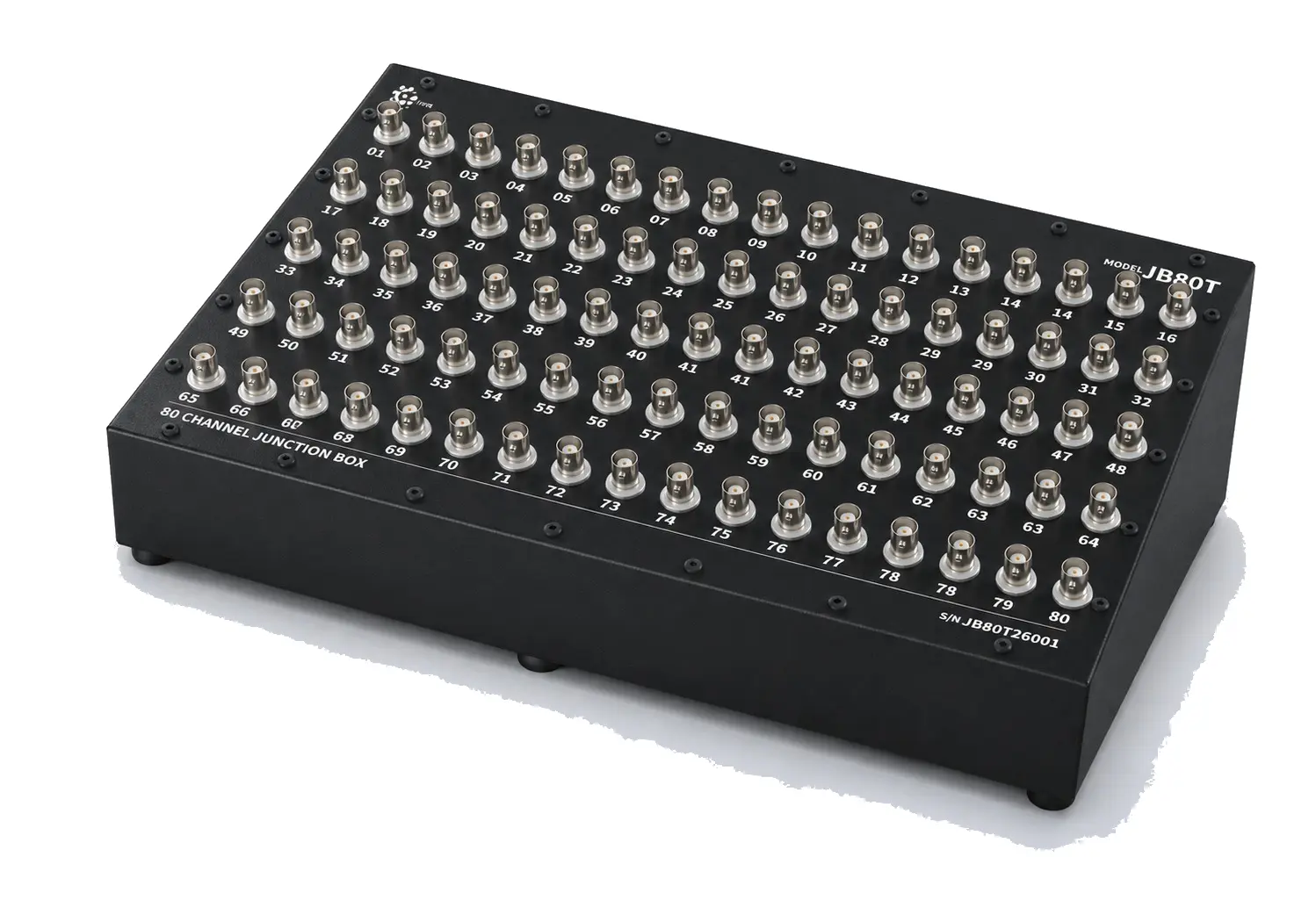
| JB80T | 80 | 5 rows × 16 | Studio render — panel numbering has legibility defects; channel count and layout are reliable, but fine per-connector digits are not |
Every model above uses the same panel legend format: model code top-right, TIERA logo top-left, channel numbers beside each BNC, {N} CHANNEL JUNCTION BOX along the lower edge, and a serial number S/N JB{NN}T26001.
Two build options, not two product lines
Standard build — screw-fixed cover. Every model, JB04T through JB80T, is built this way as standard: black powder-coated steel, a top panel held down by corner and edge screws, rubber bench feet, no hinge, no lock, no lid-support stay. It is the cheaper, simpler cover — a screwdriver removes it during setup or a wiring change, and there is nothing to fail on a bench unit that lives in a lab and isn’t opened and closed under time pressure.
Chassis-configured build — hinged, lockable, zoned. Available as an upgrade from 48 channels up, and standard on the 64-channel tender configuration: a folding lid-support stay that holds the cover open without a hand on it, a key-operated or hasp lock with two-point handles, the panel divided into zones with dividing graphics, one cable gland per zone sized to that zone’s cable bundle, and an optional wheeled castor stand for field or site deployment. Port numbering is printed on both the outer and inner face of the cover, so a technician can read channel numbers with the lid open or closed.
Why the boundary sits near 32 channels. Below that, one technician can scan a single flat panel and keep the wiring in their head — a screw-fixed cover and bench feet are the whole story. Above it, the panel is wide enough that grouping channels by structure zone or DAQ card measurably reduces wiring errors, and a box that gets opened and closed repeatedly on a test floor benefits from a lid that stays up on its own and locks when the test is unattended. JB48T and JB60T are built to the screw-fixed convention as standard — the chassis build is the configurable option at that size, not the default. JB64T is the case where a customer specified the chassis build outright, and its zoning (4 × 16) is the only zone grouping evidenced in the source material for this family.
Configuration matrix
Specify against this table when requesting a quote. Not every combination applies to every channel count — ask sales to confirm fit for your model.
| Option | Choices | Applies to | Notes |
|---|---|---|---|
| Cover | Screw-fixed panel (standard) · Hinged, lockable, with lid-support stay | All models; hinged/lockable typically only justified from 48 ch up | Hinged build adds lock hardware and two-point handles |
| Mounting | Bench feet (standard) · Rack ears · Wheeled castor floor stand | Bench feet: all models. Rack ears and castor stand: chassis build | Castor stand supplied with the unit on tender-grade orders |
| Cable glands | Sized and counted to the cable bundle | JB12T confirmed at 2 glands, one side wall. Others confirmed at order engineering | Chassis build: 1 gland per zone (JB64T: 4 glands, 16 coax each) |
| Connector make | Amphenol · Neutrik · TE Connectivity · Fairview Microwave | All models | Approved-vendor list; make and part number stated in the offer |
| Panel marking | Outer face only (standard) · Outer + inner face | Outer-only: standard. Outer + inner: chassis build (mandatory on JB64T) | Inner-face marking needed once a lid can be opened and read from inside |
| Zone grouping | None · Grouped by structure/DAQ zone | Meaningful above ~32 channels; confirmed only on JB64T (4×16) | Zone width follows the customer’s sensor layout, not a fixed rule |
| Test-report scope | Standard (≥10% of connectors or 8 channels, whichever is higher) · Full 100% channel test | All models | Full-scope test available on request, at added cost |
Electrical specification
±0.1 dB flatness, 10 Hz–20 kHz is the specification that actually defines this family — it is the one number a buyer should compare across suppliers, and every model meets it across its full channel count.
| Parameter | Value |
|---|---|
| Flatness | ±0.1 dB, 10 Hz – 20 kHz |
| Contact resistance | ≤ 5 mΩ |
| Insulation resistance | ≥ 1000 MΩ |
| Connector | BNC, female-to-female, panel-mount bulkhead — one per channel |
| Contact material | Beryllium copper or brass, nickel-plated |
| Insulator | Delrin (Acetal / POM) |
A note on THD and noise floor. These are passive assemblies — a panel of connectors and coaxial runs, with no active device anywhere in the signal path to generate distortion or noise of its own. A THD or noise-floor number measured on a box like this characterises the test system at least as much as the box: it is a null-result measurement, and a good one. TIERA reports ≤ 0.001% THD (≤ −100 dBV ref. fundamental @ 1 kHz) and ≤ −120 dBV broadband noise floor on every delivered unit, on request — read those figures as confirmation that the assembly adds no detectable distortion or noise above the calibrated analyser’s own floor, not as a spec the box “achieves” the way an active instrument would.
Two footnotes worth carrying into a tender response:
- 50 Ω impedance and a DC–4 GHz connector rating (where specified) are outside the family’s 10 Hz–20 kHz usable band — an IEPE accelerometer chain isn’t an impedance-matched RF line at audio frequencies, so 50 Ω vs 75 Ω makes no measurable difference here. The requirement is harmless but narrows the approved-connector list.
- Delrin (POM) is specified as the connector insulator rather than PTFE. PTFE has a marginally better dielectric at RF; for this band the difference is not measurable, and Delrin is standard and less costly. Flag this with the customer if PTFE is a fixed BOM requirement rather than a technical one.
Test report and compliance
Every unit ships with a test report generated on a calibrated audio/RF analyser, covering a minimum of 10% of connectors or 8 channels — whichever is higher — with worst-case values reported in both dBV and percent. The report is delivered with the unit, not after.
The 64-channel configuration was engineered against a customer tender specification. Its model page reproduces the full compliance checklist so a tender response can be mapped line by line.
Applications
- Aircraft-structure vibration and modal testing
- Modal test arrays and impact/shaker campaigns needing many simultaneous points
- Acoustic and microphone-array measurement chains
- Structural health monitoring (SHM) installations
- End-of-line test benches where a fixed sensor layout is tested repeatedly
Warranty
12 months from acceptance, covering replacement of defective connectors, cover hardware, cable glands or finish at no cost.
Pairs with:
- PhonoVibe Series — multi-channel DAQ to receive the routed BNC channels
- TVIB Software — analysis suite for the sensor data these boxes route
- Sensors & Accessories — accelerometers, cables and mounts feeding into the panel
- Signal Conditioners — IEPE conditioning ahead of the junction box where needed
Want to buy or trial it?
Email sales or book a 20-minute demo call.