











JB64T — 64-Channel BNC Junction Box, Tender Configuration
64 BNC channels, 4 zones × 16, hinged lockable lid, castor stand — built to a customer tender specification.
SKU: JB64T
- ●64 channels, 4 zones × 16, zone-labelled panel
- ●Hinged, lockable lid with folding lid-support stay
- ●Port numbering on both outer and inner face of the cover
- ●4 cable glands, one per zone, sized for a 16-coax bundle each
- ●Wheeled castor stand supplied with the unit
- ●Connector make from an approved list, stated in the offer
- ●Full delivery test report: THD, noise floor, frequency response, dBV and %
- ●1-year warranty
| Channels | 64 |
| Panel layout | 4 zones × 16 channels |
| Form factor | Chassis — hinged, lockable, zoned |
| Connector | BNC, female-to-female, panel-mount bulkhead, ×64 |
| Connector make | Amphenol, Neutrik, TE Connectivity or Fairview Microwave (approved list only) |
| Contact material | Beryllium copper or brass, nickel-plated |
| Insulator | Delrin (Acetal / POM) |
| Cover | Hinged, lockable (key or hasp), folding lid-support stay, two-point handles |
| Panel marking | Outer and inner face of the cover |
| Mounting | Floor/bench chassis; wheeled castor stand supplied |
| Cable glands | 4, one per zone, sized for 16 coaxial cables each |
| Chassis material | Cold-rolled / mild steel, minimum 2 mm, powder-coated (black default) |
| Flatness | ±0.1 dB, 10 Hz – 20 kHz |
| Contact resistance | ≤ 5 mΩ |
| Insulation resistance | ≥ 1000 MΩ |
| Warranty | 12 months from acceptance |
JB64T is the family’s chassis-configured build, engineered to a customer tender specification for a 64-channel BNC junction box for precision signal routing in vibration measurement, acoustic testing, modal analysis and structural health monitoring. Where every other model in this family ships in the standard screw-fixed T-series construction, JB64T is built the other way: a rigid rectangular chassis in cold-rolled or mild steel, minimum 2 mm thickness, powder-coated black by default, edges deburred and chamfered, supplied with a vertical castor-wheel stand for floor mobility.
Panel and cover
The top cover carries 64 BNC connectors grouped into 4 zones of 16 channels, with zone labels or dividing graphics separating the groups. Port numbering is printed on both the outer and inner face of the cover, in a font sized and contrasted to stay readable under typical field lighting — with the lid open or closed, a technician can read the channel map.
The cover itself is hinged, with a heavy-duty cabinet-grade folding lid-support stay that holds it open without a hand on it, and a lockable closure — key-operated or hasp-type — with ergonomic handles at both ends for two-point operation.
Cable management
Four cable glands, one positioned adjacent to each zone to minimise internal cable crossings, each sized for a bundle of 16 coaxial cables. Gland material is nylon or nickel-plated brass.
Electrical specification
±0.1 dB flatness, 10 Hz–20 kHz is the specification that defines this box. It is the number that determines whether the assembly is transparent to the measurement passing through it, and it is verified by measurement on every unit.
| Parameter | Requirement | Expression |
|---|---|---|
| Flatness | ±0.1 dB, 10 Hz – 20 kHz | Measured across the full usable band |
| Total harmonic distortion | ≤ 0.001% | ≤ −100 dBV ref. fundamental @ 1 kHz |
| Noise floor (broadband, A-weighted) | ≤ −120 dBV | ≤ 1 µV RMS, 50 Ω termination |
| Contact resistance | ≤ 5 mΩ | — |
| Insulation resistance | ≥ 1000 MΩ | — |
JB64T is a passive assembly: 64 connectors and coaxial runs, with no active device anywhere in the signal path to generate distortion or noise of its own. The THD and noise-floor figures above are null-result measurements — they characterise the calibrated test system at least as much as the box, and what they demonstrate is that the assembly adds no detectable distortion or noise above the analyser’s own floor. Read them as confirmation, not as a spec the box “achieves” the way an active instrument would.
Two points worth carrying into a tender response:
- The tender’s 50 Ω / DC–4 GHz connector rating sits well outside this box’s 10 Hz–20 kHz usable band. An IEPE accelerometer chain is not an impedance-matched RF line at audio frequencies, so 50 Ω vs 75 Ω makes no measurable difference here — the requirement is harmless but narrows the approved-connector list.
- Delrin (Acetal/POM) is specified as the insulator; PTFE and polyethylene are explicitly not accepted. PTFE has a marginally better dielectric at RF, but for this band the difference is not measurable, and Delrin is standard and less costly. Worth confirming with the customer if PTFE is a fixed BOM requirement rather than a technical one.
Test report
Generated on a calibrated audio/RF analyser, covering a minimum of 10% of connectors or 8 channels — whichever is higher — with worst-case values reported. Values are given in both dBV and percent where applicable, and the report is submitted with the unit, not after delivery.
Tender compliance checklist
Reproduced from the customer specification, for direct mapping in a tender response.
- Exactly 64 BNC female-to-female bulkhead adaptors, 50 Ω, Delrin insulator, nickel-plated contact
- Connector make from approved list only (Amphenol / Neutrik / TE Connectivity / Fairview Microwave)
- Port numbering on inside AND outside of top cover
- 4-zone × 16-channel grouping with 4 dedicated cable glands
- Lockable cover with handles and soft-close lid support arm
- Powder-coated steel chassis
- Test report for THD, noise floor and frequency response (10 Hz–20 kHz) in dBV and %
Typical applications
- Aircraft-structure vibration and modal testing
- Large modal test arrays and impact/shaker campaigns
- Acoustic and microphone-array measurement chains
- Structural health monitoring (SHM) installations
- End-of-line test benches with a fixed, repeated sensor layout
See current pricing and configuration options on the TIERA store.
Pairs with:
- Junction Box family — full line-up, configuration matrix and electrical spec
- JB48T · JB80T — neighbouring channel counts
- PhonoVibe Series — multi-channel DAQ to receive the routed channels
-
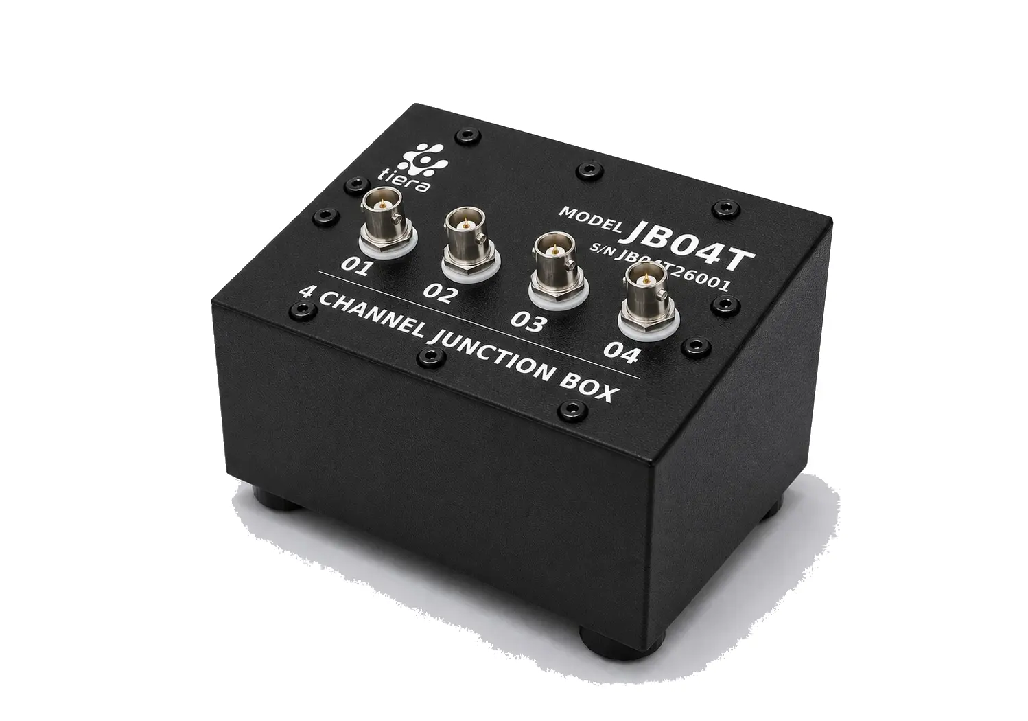 JB04T — 4-Channel BNC Junction Box The smallest box in the family — 4 BNC channels in a single row, screw-fixed cover.
 -
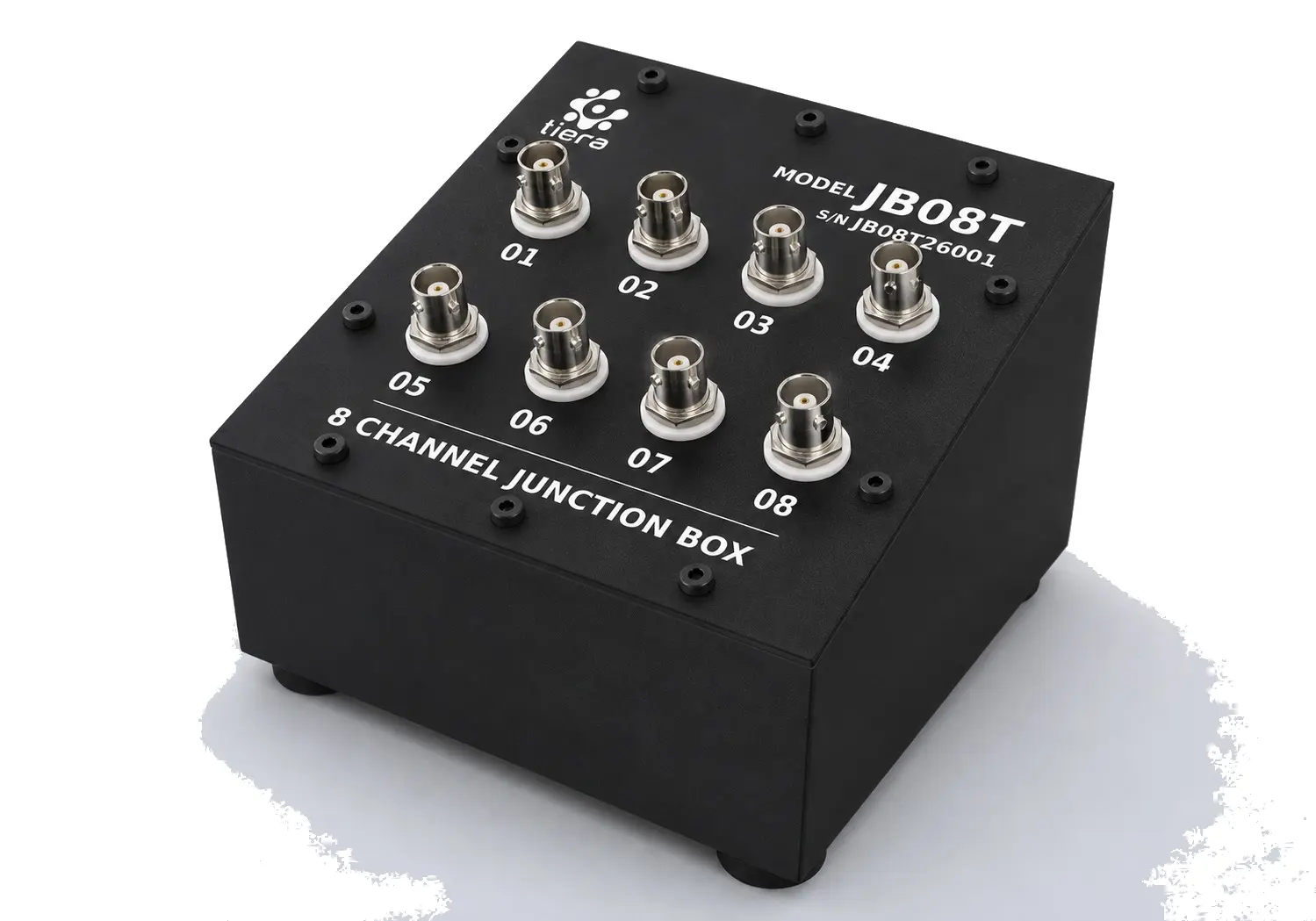 JB08T — 8-Channel BNC Junction Box 8 BNC channels, 2 rows × 4, screw-fixed cover — a compact bench routing panel.
 -
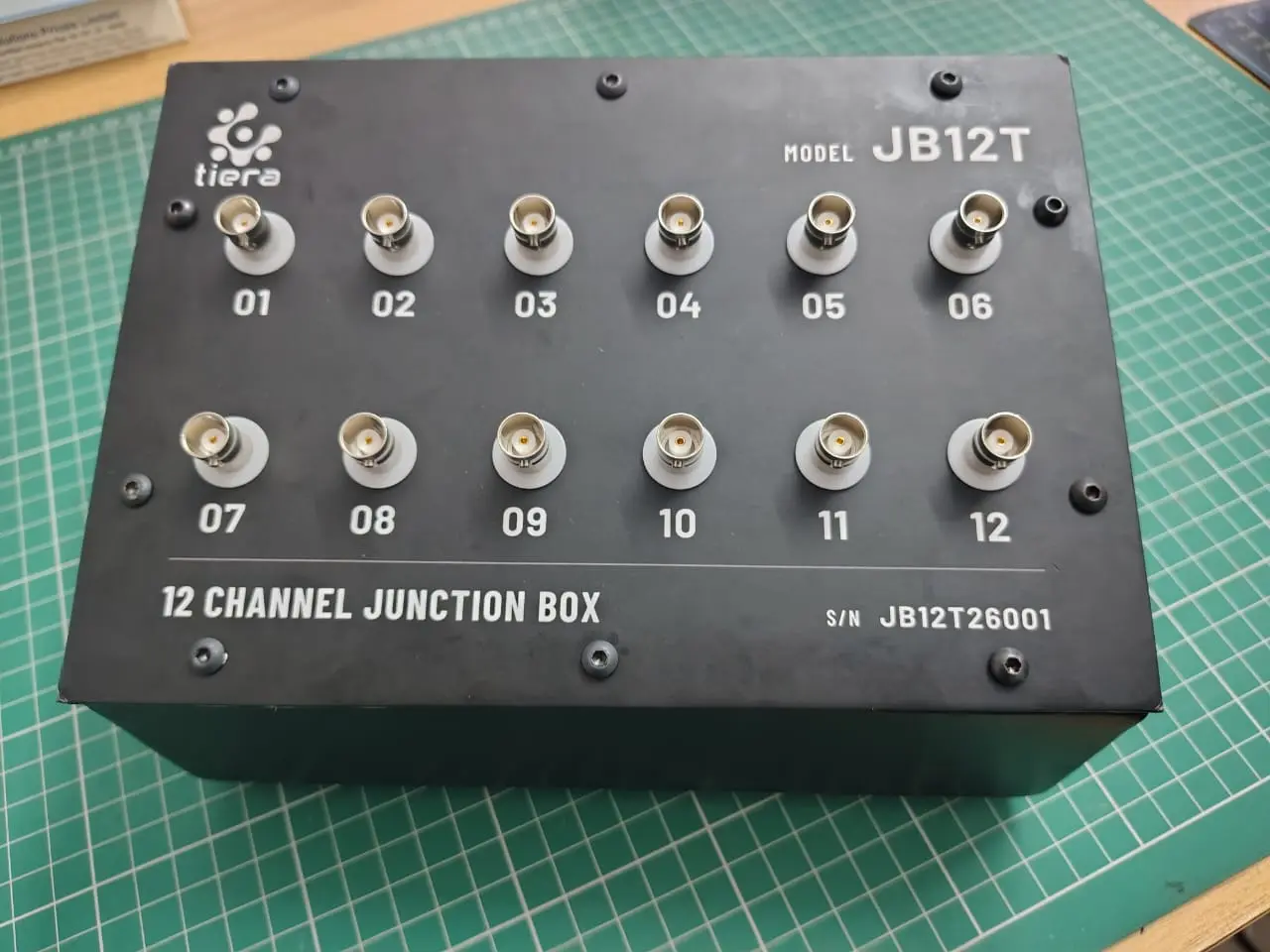 JB12T — 12-Channel BNC Junction Box 12 BNC channels, 2 rows × 6, screw-fixed cover, two cable glands — the family's most fully photographed model.
 -
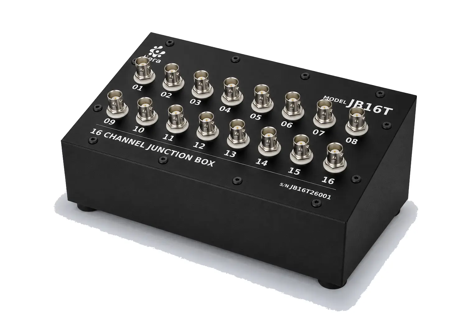 JB16T — 16-Channel BNC Junction Box 16 BNC channels, 2 rows × 8, screw-fixed cover — matched to a 16-channel DAQ.
 -
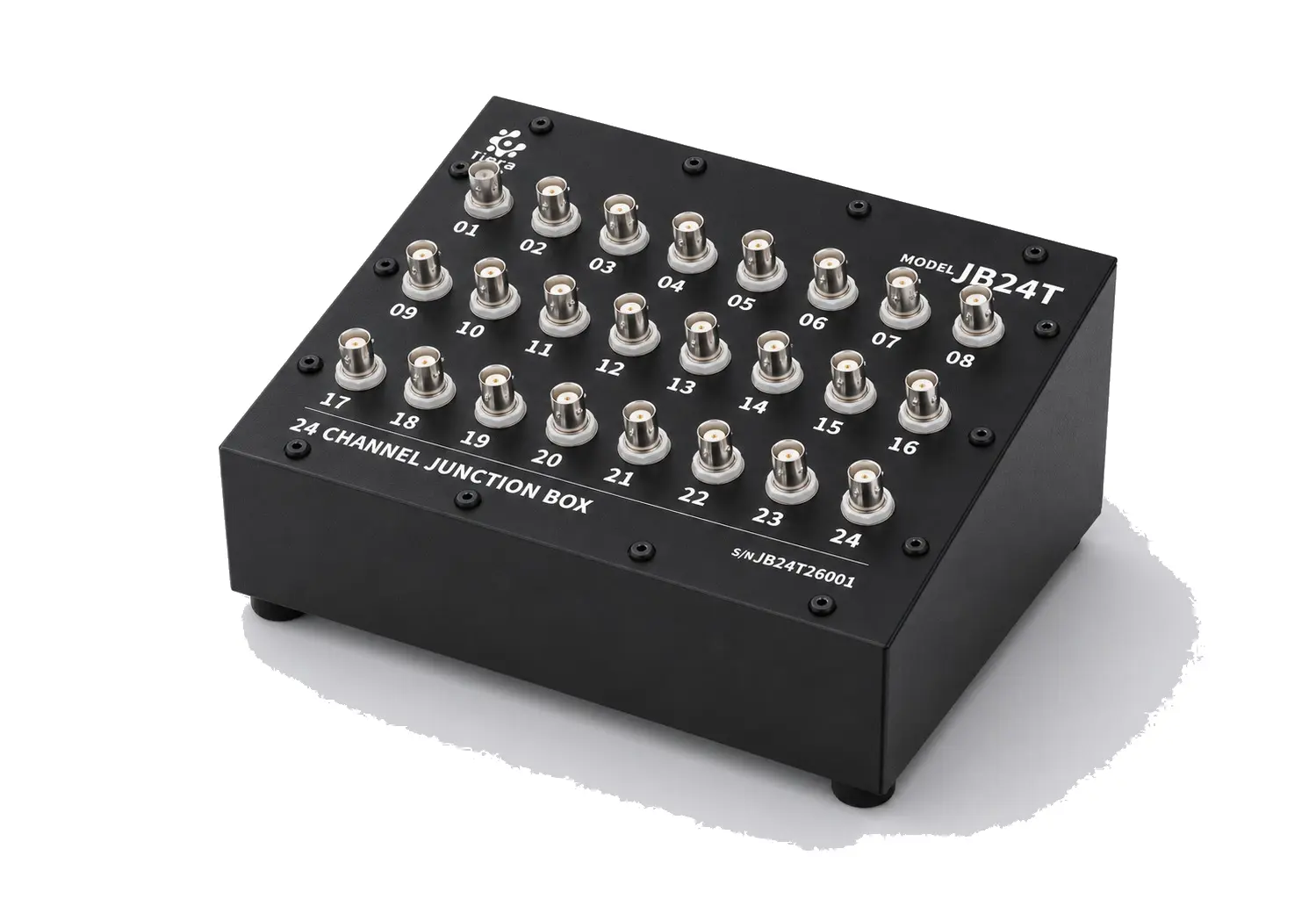 JB24T — 24-Channel BNC Junction Box 24 BNC channels, 3 rows × 8, screw-fixed cover — the largest standard bench layout in the family.
 -
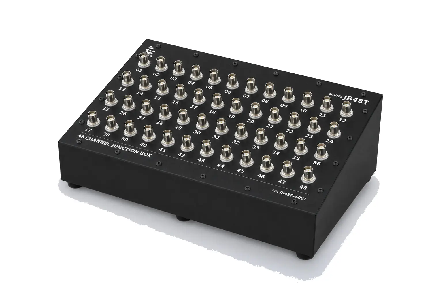 JB48T — 48-Channel BNC Junction Box 48 BNC channels, 4 rows × 12, screw-fixed as standard — chassis build available.
 -
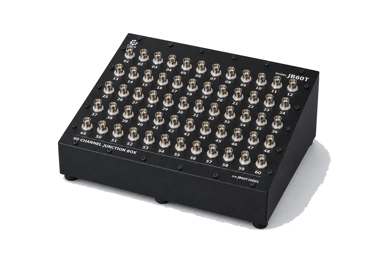 JB60T — 60-Channel BNC Junction Box 60 BNC channels — a chassis build is also available above 32 channels.
 -
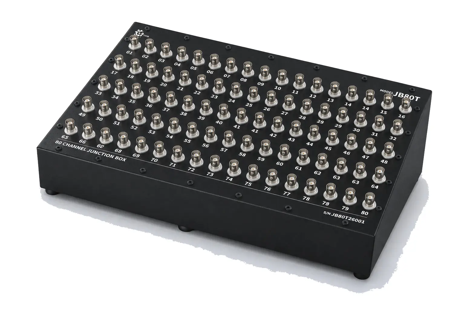 JB80T — 80-Channel BNC Junction Box 80 BNC channels, 5 rows × 16, screw-fixed as standard — the largest model in the family.
Want to buy or trial it?
Email Varghese (sales) or book a 20-minute demo call.