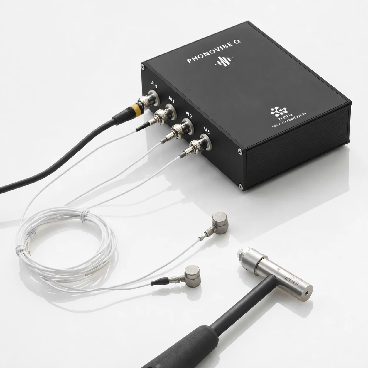
A defence or aerospace test article gets one shot. The fixture is booked, the article is instrumented, the range slot or the shaker time is allocated — and if a channel drops out, a ground loop hums at 50 Hz, or a sensor saturates on the first transient, the test is not repeatable at any price.
That changes what matters in the instrument. Channel count, wiring discipline and traceable calibration matter more than a clever screen.
What this sector measures
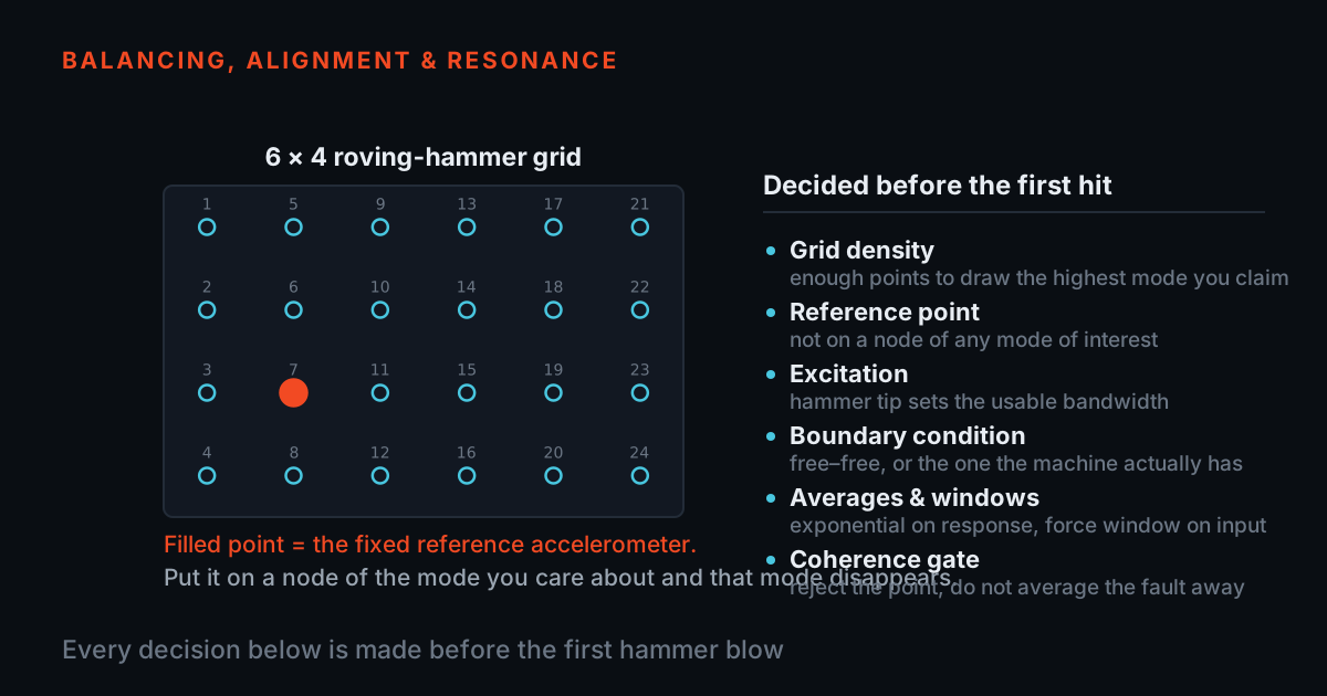
Structural dynamics and modal survey. Impact or shaker excitation, FRF at every measurement point, mode shapes extracted from the set. The decisions that determine whether the test works — where to excite, where to measure, how many averages, which window — are made before the hammer moves. The modal analysis and structural dynamics workflow covers the route in detail.
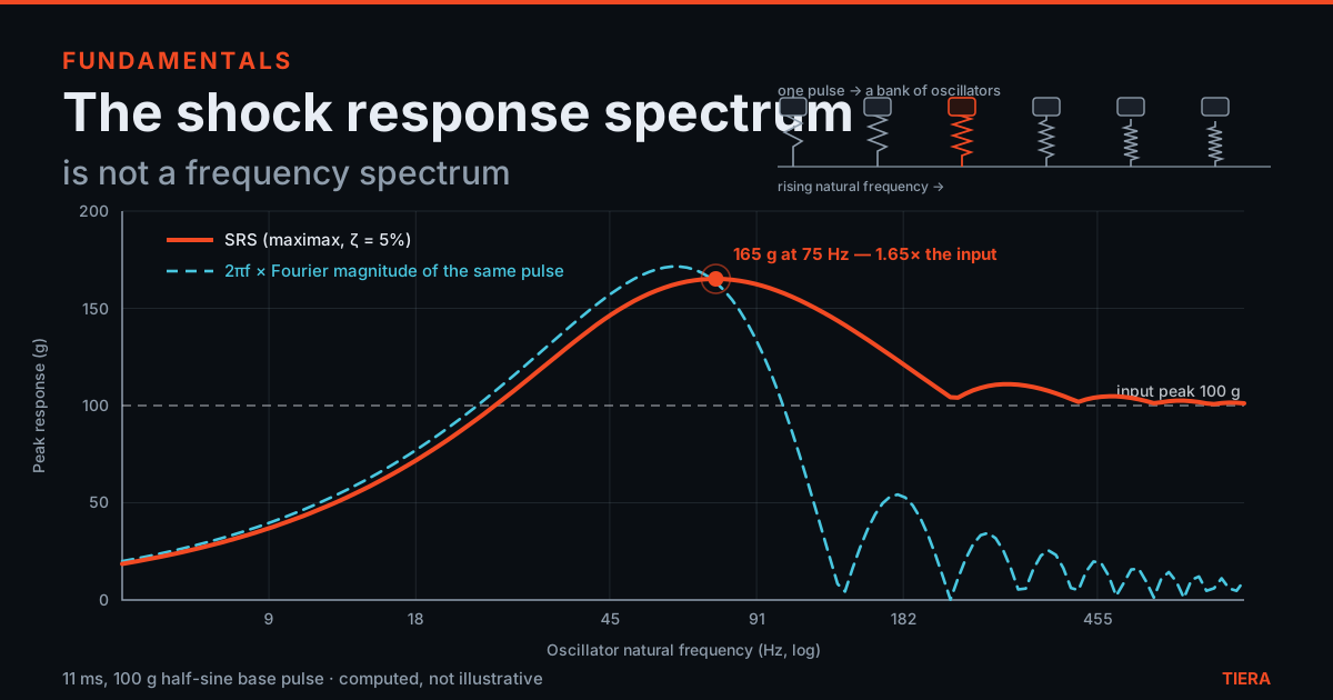
Qualification and environmental testing. Sine sweep, random and shock profiles on a shaker, with the control and response channels recorded together. A shock reading is the one most likely to lie: a sensor driven past its range or a DC-coupled path that shifts zero produces a spectrum that looks plausible and is wrong.
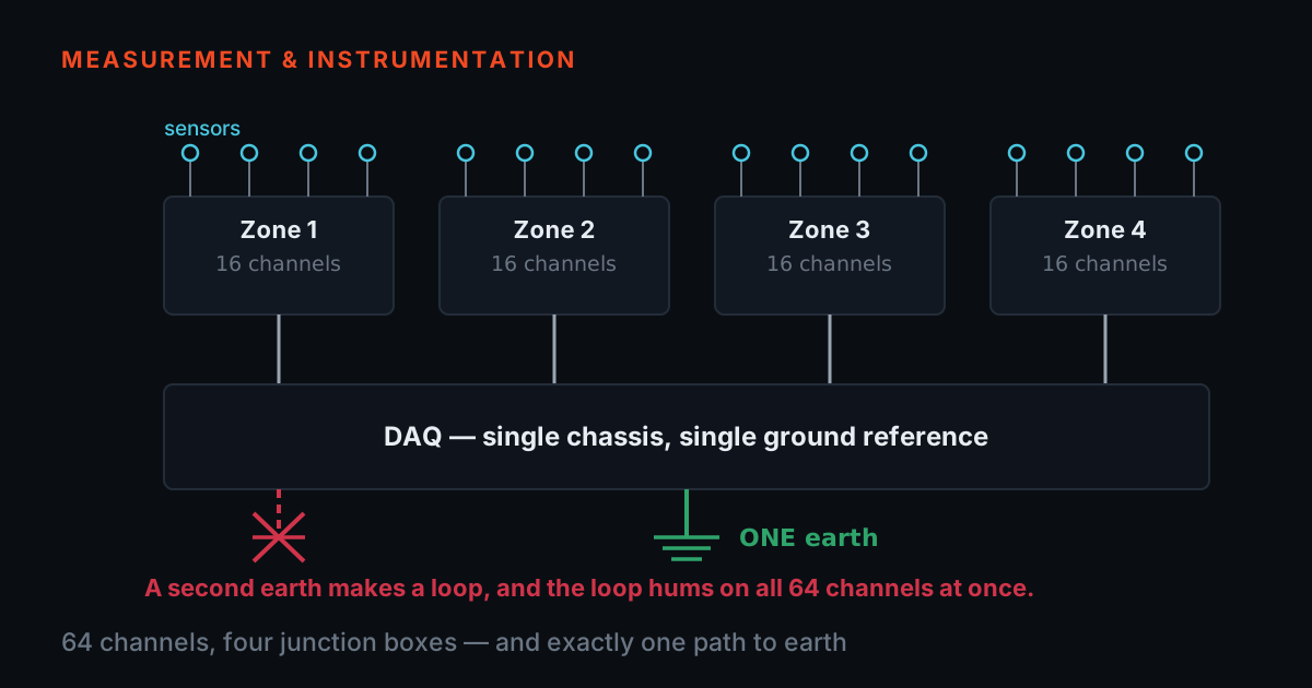
High-channel-count array tests. Twenty, forty, eighty accelerometers on a structure means eighty cables, eighty connector labels and one grounding scheme. The failure mode is not electronics; it is a patch panel nobody documented.
The instrumentation
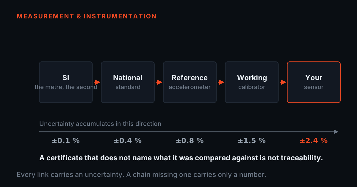
A defence or aerospace chain is usually built from four parts. The PhonoVibe DAQ family supplies simultaneous IEPE channels — 2, 4, 8 or 16 per unit, with PhonoVibe HD at the top. The JB junction-box family patches 4 to 80 BNC channels into a labelled panel, which is what turns a large array from a cable pile into a test setup. TSP signal conditioners and the IEPE power source drive charge and IEPE sensors where the DAQ does not. T-Calibro keeps the whole chain traceable, in India, on a schedule you control.
TVIB analyses what comes back — time waveform, spectrum, order analysis, FRF and modal post-processing — and exports it in a form a qualification report can carry.
The standards this work is judged against
Vibration severity for rotating machinery follows the ISO 20816 series, which sets evaluation zones by machine class and mounting rather than by a single number. Modal and FRF measurement practice follows the ISO 7626 series, which is concerned with excitation, mounting and the way a driving-point measurement is made. Analyst competence is defined by ISO 18436-2. TIERA describes these standards and builds to them; it does not publish or resell the standards themselves, and a qualification programme should always work from its own controlled copy.
Where to start
If the test is a modal survey, start with the modal analysis workflow and the post on planning a modal test. If it is a large array, start with the junction boxes and the post on wiring a 64-channel test — the grounding decision is cheaper to make now than to debug at 3 a.m.
The workflows behind this
Each one is a full measurement route with its own instrument list.
Modal Analysis and Structural Dynamics R&D
Hammer and shaker-based FRF testing, frequency-response characterisation, and mode-shape extraction for mechanical R&D teams and structural dynamics labs.
Open the workflow →End-of-Line Quality Testing
Automated spectral alarm pass/fail on every unit leaving the production line — driveshafts, pumps, motors, gearboxes — using PhonoVibe DAQ and TVIB NDT RAM.
Open the workflow →