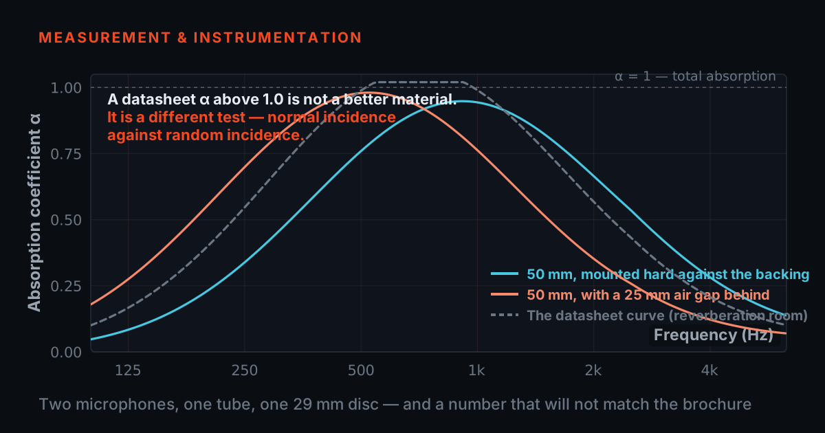
A material’s acoustic performance is a measurement, and the number that appears on a datasheet is only as good as the method behind it. The two questions that get confused are worth separating before any equipment is chosen.
Absorption is how much sound energy the material does not send back. It is what an impedance tube measures, at normal incidence, on a small sample.
Transmission loss is how much sound the material stops from getting through to the other side. It is an airborne-sound quantity in dB, measured differently, and a material can be excellent at absorption and poor at transmission.
The post on acoustic impedance, transmissibility and materials separates these properly, including the structural “transmissibility” that shares a name with none of them.
Impedance-tube measurement
T-Sonus is TIERA’s impedance tube: a sample holder, a loudspeaker, two microphone positions and the analysis that turns a transfer function into an absorption coefficient against frequency.
Two things set what it can tell you, and both are geometry rather than software. The tube diameter sets the upper frequency limit, because above the first cross-mode the plane-wave assumption the whole method rests on stops holding. The microphone spacing sets the lower limit. That is why a tube is specified by its usable band first — a measurement outside the band is not a noisy result, it is an invalid one. Measuring sound absorption in an impedance tube covers the practicalities, including what a bad sample fit does to the answer.
Sound and vibration on one time base
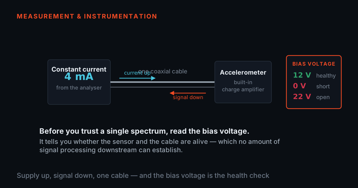
For product noise work — a panel, an enclosure, a cover, a fan — the useful measurement is usually both: what the surface is doing and what reaches the ear. PhonoVibe takes IEPE microphones and accelerometers on the same channels and the same clock, so the two records can be compared rather than merely collected together. TSP signal conditioners cover the sensors the DAQ does not power directly, and what a signal conditioner actually does explains when you need one.
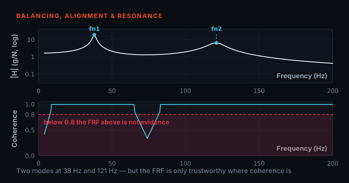
Where the question is which mode of the structure is radiating, the modal analysis workflow applies unchanged — and coherence is the number that tells you whether an FRF is worth interpreting at all.
The standards this work is judged against
Impedance-tube absorption measurement follows the ISO 10534 series, which is concerned with the plane-wave method and the geometry constraints described above; reverberation-room absorption follows ISO 354 and answers a different question. Analyst competence in vibration is defined by ISO 18436-2. TIERA builds to these and describes them; a testing programme should work from its own controlled copies, and a customer specification always governs.
Where to start
If a specification names an absorption figure, check first which method it means — tube or room. If it is the tube, the band you need decides the tube, and that decides everything after it. A conversation before the purchase order is cheaper than a tube whose upper limit sits below the band your customer asks about.
The workflows behind this
Each one is a full measurement route with its own instrument list.
Modal Analysis and Structural Dynamics R&D
Hammer and shaker-based FRF testing, frequency-response characterisation, and mode-shape extraction for mechanical R&D teams and structural dynamics labs.
Open the workflow →End-of-Line Quality Testing
Automated spectral alarm pass/fail on every unit leaving the production line — driveshafts, pumps, motors, gearboxes — using PhonoVibe DAQ and TVIB NDT RAM.
Open the workflow →