The Mount Is Part of the Instrument: Magnets, Pads and Studs for Wireless Sensors
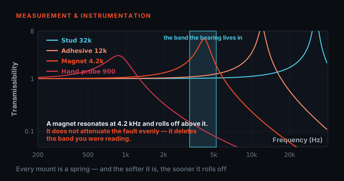
A wireless vibration node is a spring-mounted mass, and the spring is whatever you put between it and the machine. Stud, adhesive pad, flat magnet, curved-surface magnet, magnet-on-paint — each has a mounted resonance, and that resonance decides which frequencies reach the sensor honestly, which arrive amplified, and which never arrive at all. A driveable model, the paint trap, and the mounting hardware that fixes it.
A wireless node is a heavier sensor with no cable to blame
When a wired accelerometer reads nonsense, the suspects line up: cable, connector, conditioner, mount. A wireless node removes every suspect but one. There is no cable, no connector corroding in the monsoon, no IEPE supply to sag — the entire signal path between the machine's surface and the sensing element is the mount. That concentration is a gift for troubleshooting and a trap for installation: whatever the mount does to the signal is in every reading the node ever radios out, and nothing downstream can undo it.
And a wireless node asks more of its mount than a bare accelerometer does. It is a package — sensing element, battery, radio, case. CTC's entry ConnectSens sensor weighs 130 g by its datasheet; a general-purpose wired accelerometer is typically well under half that. The physics is unforgiving about mass: the mount behaves as a spring of stiffness k under a mass m, with a mounted resonance at √(k/m). Double the mass on the same joint and the resonance drops by a factor of √2 — the heavier package drags the resonance down toward the very frequencies you bought the sensor to measure. Manufacturers know this; it is why CTC publishes a dedicated mounting-hardware range for wireless sensors and why their triaxial FAQ carries a caveat we will come back to. The one-line summary of this whole post: the mount sets the bandwidth, and with a wireless node you only choose the mount once.
The general theory — every mount is a spring, trust up to about a third of the mounted resonance — is covered with a simulator in /blog/sensor-mounting-bandwidth-simulator, and choosing between magnet types in /blog/magnetic-mount-selection. This post applies both to the wireless case specifically, where the choice is permanent, the mass is higher, and the readings are unattended.
Five mounts, ranked — and the lie a mount tells before it goes deaf
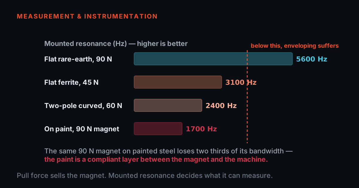
From stiffest to softest: a stud into a drilled, spot-faced boss — metal-to-metal, the reference every datasheet quotes; CTC's wireless sensors carry a 1/4-28 tapped base for exactly this, with a specified mounting torque of 2–5 ft·lb. An adhesive pad — a thin, hard bond line on prepared metal, nearly as stiff, the answer where drilling is forbidden. A flat magnet on clean bare metal — stiff enough for most process machinery, and removable. A two-leg curved-surface magnet on a motor housing or shaft guard — the legs grip a curve a flat magnet cannot, at some further cost in stiffness. And last, the trap: any magnet on paint. The magnet's pull is fine; the joint's stiffness is set by the softest layer in the stack, and a coat of alkyd enamel under a magnet is a compliant layer that can drag the mounted resonance from kilohertz down into the hundreds of hertz — into gear-mesh and bearing territory.
Here is the subtlety that catches even experienced crews: a compromised mount does not simply mute the high frequencies. Just below its resonance, a mass-on-spring system amplifies — readings in that region come back 10–20 dB high, exciting and wrong. A magnet-on-paint mount with its resonance at 800 Hz will faithfully report your 24 Hz unbalance, inflate vibration near a few hundred hertz, and delete the 2.8 kHz bearing ring entirely. The dangerous zone is the middle one, because nothing about the reading looks broken — the trend simply runs high, alarms fire on healthy machines, and confidence in the whole wireless programme erodes one false alarm at a time. Never assume a mount only subtracts; near resonance it adds.
Drive the model: mount, frequency, verdict
The model below is a single-degree-of-freedom mounted-resonance response — the standard textbook treatment, computed live. Pick a mount, drag the test frequency, and read what the sensor would report relative to the truth. The resonance values are indicative, typical orders of magnitude for a ~130 g wireless node — not the specification of any CTC or TIERA product. Real mounted resonance depends on the exact sensor mass, the surface, the torque, and the paint thickness; on a point that matters, measure it with a bump test rather than assuming it. One CTC-stated number is drawn on the chart for orientation: the ConnectSens family's own sensor resonant frequency, 5.5 kHz — a reminder that even a perfect stud mount does not buy unlimited bandwidth, because the sensor's usable band ends below whichever resonance comes first, the mount's or its own.
Single-degree-of-freedom mounted-resonance model, computed live. Resonance values are INDICATIVE for a ~130 g wireless node — not a CTC or TIERA specification. On a critical point, bump-test the installed mount and let the measurement govern.
—
Paint, curvature, and the Z-axis caveat
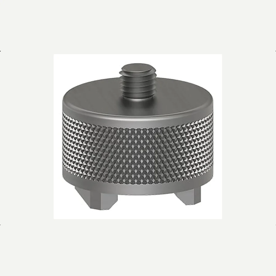
Three field realities decide most wireless installations. Paint first. Indian plant machinery is painted, repainted, and painted again — five coats of enamel on a twenty-year-old motor is not unusual, and every coat is compliance under your magnet. The professional fix is a spot face: a shallow machined pad of clean, flat, bare metal at the measurement point, cut with a spot-facing tool in minutes. Where machining is not permitted, a firmly bonded adhesive mounting pad achieves most of the same stiffness — CTC's wireless mounting hardware range includes adhesive pads for exactly this, and motor-fin pads that bridge the cooling fins where no flat surface exists at all. What is never acceptable on a permanent node is the habit that route crews get away with: slapping the magnet on the paint and trusting the trend, because on a permanent installation there is no analyst's hand feeling the wobble.
Curvature second. A flat magnet touches a curved motor casing along a line, not a surface — the joint stiffness collapses and the contact rocks. Curved-surface (two-leg) magnets exist for this geometry: the legs straddle the curve and grip with defined contact. CTC's multipurpose magnet range spans pull strengths from around 23 kg to 54 kg (their stated figures for the MH114/MH115/MH140 families), all with the standard 1/4-28 tapped hole the wireless sensors screw into, rated to 130 °C — comfortably above any Indian ambient, though worth checking against uninsulated steam-side surfaces.
Axes third. A triaxial wireless node measures three directions through one joint, and the joint is not equally stiff in all of them. CTC's own wireless FAQ notes that the Z-axis (the mounting axis) frequency response differs from X and Y — put plainly, the sideways axes run out of honest bandwidth before the axis you screwed down. TIERA's practical rule: orient the mounting axis along the direction whose high-frequency content you care most about — usually the bearing load zone — and treat the transverse axes as trend data rather than diagnostic data at high frequency. And whichever orientation you choose, mark it: unattended sensors get knocked, removed for painting, and remounted 90 degrees off, and a trend that silently changed axis is worse than no trend.
Repeatability: the quiet reason permanent mounts beat better sensors
The strongest argument for mounting discipline has nothing to do with bandwidth. A trend is only as good as the repeatability of its measurement, and mounting position is the largest repeatability error in most programmes — move an accelerometer 25 mm along a bearing housing and the reading changes more than most faults change it in a month. A permanently installed wireless node eliminates that error completely: same point, same orientation, same joint, every reading for years. This is the genuinely underrated advantage wireless nodes hold over even a excellent route programme, and it is worth protecting with the installation care this post describes — a permanent node on a bad mount repeats the same wrong measurement with beautiful consistency.
It also means the one-time cost of doing it properly amortises over every reading the node ever takes. A spot-face, a dab of threadlocker on the stud, torque to CTC's specified 2–5 ft·lb, an orientation mark, and a photograph in the asset record: perhaps twenty minutes per point, once. Against a four-year battery life at two readings a day, that is under half a minute of installation effort per thousand readings. There is no cheaper improvement anywhere in a wireless programme — and no way to add it later without breaking the trend you spent a year building. The same logic, run for magnets and cables on the wired side, is at /blog/why-cheap-cables-and-magnets-cost-more.
What to actually order, per surface
Translating this into a bill of materials, TIERA's default allocation for a wireless rollout: drilled and tapped or spot-faced points wherever plant rules allow — the sensor's own 1/4-28 base, no hardware needed beyond the spot-face tool. Flat-surface magnets on clean flat bare metal — machined feet, flat casings. Two-leg curved-surface magnets on motor housings, pump volutes and anything cylindrical. Adhesive pads on no-drill assets and thin sheet guards; motor-fin pads on finned TEFC frames. One detail that widens the audience for this advice: CTC's wireless mounting hardware brochure states the range fits wireless sensors from other manufacturers as well — ACOEM, Bently Nevada, Emerson, SKF and others — so a mixed-vendor site can standardise its mounting discipline on one hardware family even where its sensors are not standardised.
Whatever you order, order the installation with it: the spot-face tool, the torque wrench, the threadlocker. The hardware list is short and the discipline is the product. A wireless programme that budgets ₹40,000 for a sensor and nothing for its mount has decided, without meaning to, that the sensor's last usable octave was not worth twenty minutes.
TIERA instruments that do this work.
CTC Multipurpose (Curved-Surface) Magnets
The two-leg magnets for curved motor housings and volutes — the geometry a flat magnet cannot grip. Standard 1/4-28 mount, fits CTC and other vendors' wireless sensors alike.
- Max temperature
- 266 °F (130 °C)
- Mounting
- 1/4-28 tapped hole
- Family
- MH112 / MH114 / MH115 / MH140 / MH214 and variants
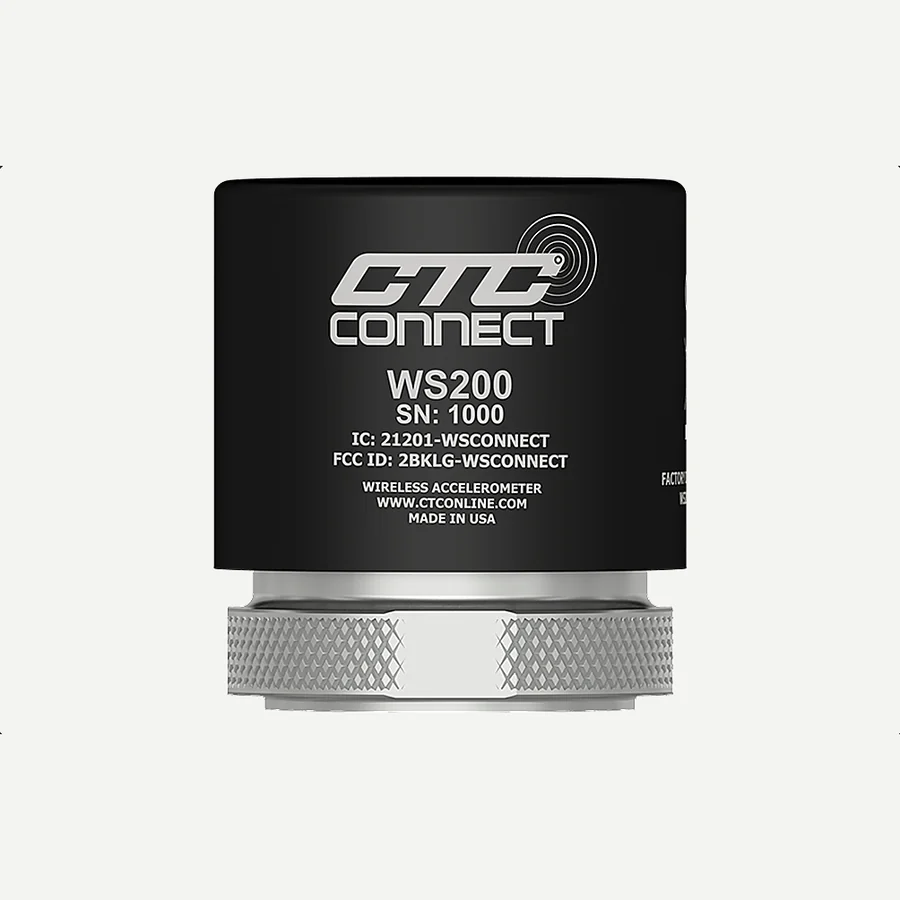
CTC WS200 Series ConnectSens Wireless Sensor
The dynamic wireless node these mounts are protecting — its high-frequency evidence only survives if the joint under it is stiff.
- Type
- Single-axis dynamic vibration + temperature
- Radio
- Bluetooth Low Energy 5.2, 1,200 ft (366 m) line-of-sight
- Battery
- User-replaceable, up to 4 years (CTC, at 2 readings/day)
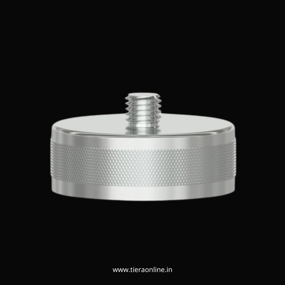
Magnetic Mount for Vibration Sensor
TIERA's route-work magnet for the wired verification measurement that closes out what a wireless node flags.
- Use
- Route measurements and diagnostics
- Thread
- Standard accelerometer mounting
From the TIERA store
The kit for this job
What we would actually put in front of someone doing the measurement this post describes — not the whole catalogue.
- Magnetic Mounting Pad for Vibration sensorTMA-101-1A : SS 304 Magnetic Mount for Accelerometers and Vibration Sensors.₹800View →
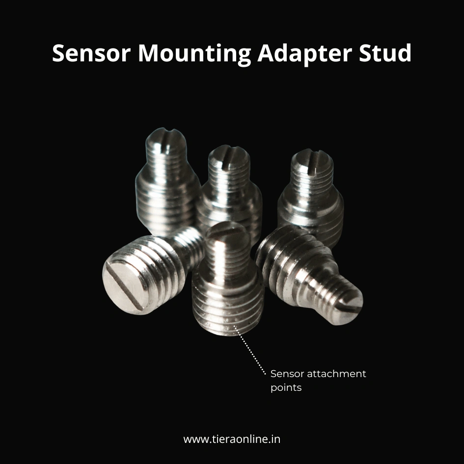 Sensor Mounting Adapter StudTM101-1A : TIERA SS304 Adapter Stud for sensor mounting₹260View →
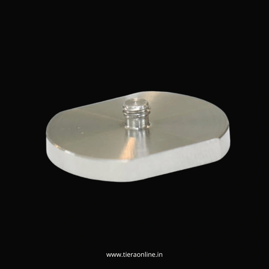 Cementing pad for Accelerometer mountingTAP-101-1-A : SS 304 Cementing pad for Accelerometers and Vibration sensors₹500View →
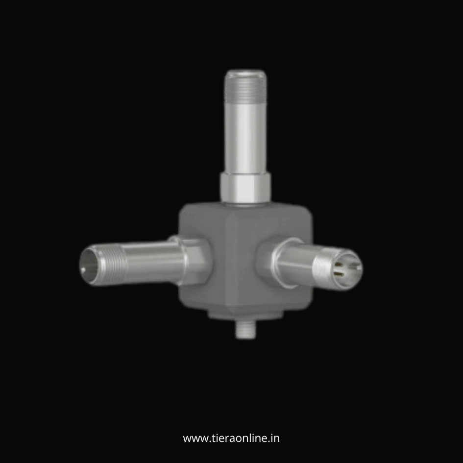 Triaxial Accelerometer Mounting BlockTMB-101-1-A : SS304 Triaxial Mount for Accelerometer Mounting Low Cost Customizable Allows attachment of 3 single axis accelerometers₹2,500View →
Use cases
Where this shows up in the field
The mounting hardware is the cheapest part of the order — and the part that decides what the sensors can see
TIERA supplies CTC's wireless mounting hardware range in India alongside the Connect sensors themselves: flat-surface and curved-surface magnets, adhesive and motor-fin mounting pads, and installation tool kits. Because the range is cross-compatible, it serves mixed-vendor sites too — if your plant already runs wireless sensors from another manufacturer, the mounting discipline in this post still applies and this hardware still fits.
Send us your point list with surface types — flat, curved, finned, painted, no-drill — and we will return a mounting bill of materials with the reasoning per point, plus the tools to install it properly.
- CTC flat and curved-surface magnets, adhesive and motor-fin pads — all 1/4-28
- Cross-brand: fits wireless sensors from ACOEM, Bently Nevada, Emerson, SKF and others (CTC's stated compatibility)
- Installation tool kits: spot-face tooling and torque control for a joint that lasts the battery's lifetime
- A per-point mounting BOM for your rollout, from your surface list
Where this sits on the TIERA learning ladder.
The theory behind this article is covered free, in full, by the TIERA 101 primers: Measurement Setup 101, Accelerometer & DAQ Selection 101. They are self-paced, interactive, and end in an exam and a certificate.
The free primers cover mounting and measurement setup; TCAT Cat I drills the field discipline — surface prep, orientation, repeatability — that makes every reading after it trustworthy.
TIERA 101 is a free introductory primer, not an accredited ISO certification, and its hours do not count towards the formal training ISO 18436 requires.