Choosing a Magnetic Mount: Pull Force Is the Easy Half
A magnet is not an accessory — it is the last spring between the machine and your accelerometer. A buyer's guide to pull force, flat versus two-pole curved geometry, surface condition and the five tests to demand, with a live bench that shows a flat magnet on a pipe collapsing your usable band.
A magnet is part of the sensor, not an accessory
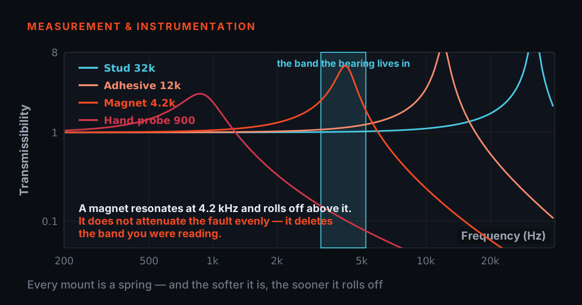
- Model the mount as a spring. Mass on a spring has a natural frequency — roughly the square root of contact stiffness divided by sensor mass — and everything the sensor reports has to pass through it.
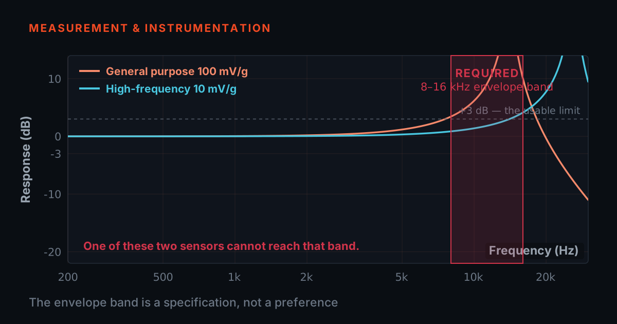
- The practical working limit is about one third of that mounted resonance, where the resonance has lifted the reading by only about a decibel.
A magnetic mount looks like the cheapest item in the kit bag, and it is usually bought that way — by holding power, or by price, or by whichever one the last engineer left in the drawer. That is a mistake with a measurable cost. Physically, the mount is the last mechanical link in the measurement chain: it has to make a stiff, light connection between the machine surface and the base of the accelerometer, and everything the sensor reports has to pass through it first.
Model it the way a mechanical engineer would. The accelerometer is a mass. The contact between the magnet and the machine is a spring — not a perfect rigid weld, but a finite stiffness set by how much real metal-to-metal area is actually touching and how hard it is being pressed together. Mass on a spring has a natural frequency, the mounted resonance, and its value is roughly the square root of contact stiffness divided by sensor mass. Below that frequency the sensor follows the surface faithfully. Near it the reading is amplified. Above it the sensor stops following at all and the response collapses.
That single number, the mounted resonance, is what a magnet buys or destroys. The practical working limit is about one third of it, where the resonance has lifted the reading by only about a decibel. If a companion post is where you first met this idea — the mounting-method comparison at /blog/sensor-mounting-bandwidth-simulator, which puts stud, adhesive, magnet and handheld probe side by side — this post picks up where that one stops. There the question was which mounting method. Here the method is already decided: you are using a magnet, and the question is which magnet, on which surface, and how you would ever know it was any good.
Pull strength: what the number means, and which direction matters
Every magnet is sold with a pull force, quoted in newtons or kilograms-force. Read it carefully, because it is a laboratory number measured under laboratory conditions: the magnet is placed on a thick, flat, ground mild-steel plate, with no coating, no oil, no curvature and no air gap, and pulled straight off, perpendicular to the surface, until it releases. That is the best case the magnet will ever see. It is a legitimate figure and a useful one — it just does not describe your pipe.
There is a second figure, and on most real machines it is the one that governs: the shear or slide force, measured by pulling the magnet sideways along the surface rather than away from it. A magnet resists sliding only through friction, and friction is the pull force multiplied by a coefficient that is typically somewhere between 0.15 and 0.35 for dry steel — lower on paint, lower again on loose oxide or oil. A magnet rated at 250 N perpendicular may hold only about 40 to 90 N in shear. On a vertical bearing housing or an overhead pipe, the weight of the sensor and its cable is trying to slide the magnet down the surface, not lift it off it, so the shear figure is the one that decides whether the sensor stays where you put it.
Ask for both, and ask on what surface each was measured. A supplier who can tell you the perpendicular figure on a flat ground plate, the perpendicular figure on the curved diameter you actually use, and the shear figure on both, is a supplier who has tested the mount rather than repeated the magnet manufacturer's brochure. A supplier who can only quote one number, with no surface stated, has told you very little.
Why pull force is not the same as bandwidth
- Flux crosses a gap; stiffness does not. A magnet will grip through 200 micrometres of paint and feel immovable in your hand while sitting on almost no real metal-to-metal contact.
- Lose ninety per cent of the contact area to curvature and the mounted resonance drops by roughly a factor of three — a usable ceiling of about 1.4 kHz becomes about 400 Hz, and the bearing harmonics above it are simply not in the recording.
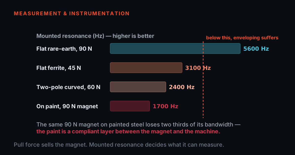
Here is the part that catches most buyers. Holding force and measurement quality are set by two different things. Holding force is about total magnetic flux crossing the joint, and flux will cross a gap — the magnet will happily grip through 200 micrometres of paint and still feel immovable in your hand. Bandwidth is about contact stiffness, and contact stiffness is about real metal-to-metal contact area, which needs the two surfaces to be within a few tens of micrometres of each other. A magnet can be strong and, at the same time, be sitting on almost nothing.
The consequence is uncomfortable and worth stating plainly: a magnet that feels strong can still halve your usable frequency range. The stiffness of the joint is roughly proportional to how much of the pole face is genuinely touching, and only weakly dependent on how hard it is pressed. Lose ninety percent of your contact area to curvature and you lose most of your stiffness, which drops the mounted resonance by roughly a factor of three, which drops your usable ceiling by the same factor — from something like 1.4 kHz to something like 400 Hz. Bearing defect harmonics and impact energy live above that. They are simply not in the recording.
That is why 'how strong is it' is the wrong first question. The right first questions are: how much of the face touches on my surface, and what mounted resonance does that give with my sensor. Pull force still matters — it sets the preload that holds the contact closed, and it decides whether the sensor stays on the machine — but it is the easy half of the specification.
Curved or flat: the geometry decides the contact patch
- Flat full-face belongs on machined pads, flat gearbox faces and bonded target pads. Two-pole curved belongs on housings, bearing caps and pipes, because a narrow rail only has to conform over a few millimetres and so stays in contact across a wide range of diameters.
- Put either on the wrong surface and it still feels firm and still shows a healthy running-speed peak. Neither failure announces itself.
There are two common magnet geometries and they are not interchangeable. A flat, single-pole, full-face magnet presents one large flat pole face. On a flat machined surface it is the best magnetic mount there is: the entire face contacts, the contact area is large, the stiffness is high, and the mounted resonance is as high as a magnet gets. That is the mount for a machined pad, a flat gearbox face, a motor end bracket, or a bonded target pad you installed for the purpose.
A two-pole curved magnet — often called a rail or dual-rail magnet — presents two narrow pole rails, profiled or angled to sit on a cylinder. On a curved surface such as a motor housing, a bearing cap or a pipe, the two rails straddle the curve and both make contact along their length. The contact area is smaller than a full flat face, but it is real contact, and crucially it stays real across a wide range of diameters, because a narrow rail only needs to conform over a few millimetres.
Put each one on the wrong surface and you get the same failure in mirror image. A flat magnet on a 100 mm pipe touches on a single line down the middle: it still grips — it keeps roughly half its pull force, because flux crosses the wedge-shaped gap either side — but the metal-to-metal contact is a sliver, the assembly rocks about that line, and the mounted resonance falls to roughly a third of what the same magnet gives on a flat face. A two-pole magnet on a flat surface touches only along the two outer edges of its rails, which costs you contact area for no reason at all. Neither failure announces itself. The magnet feels firm in both cases, and the spectrum still has a low-frequency peak at running speed that looks perfectly healthy.
Try it: the mount selector bench
The bench below puts the argument in one place. Choose a magnet, choose the surface it is going on, set the paint thickness and the mass of your accelerometer, and then move the defect frequency you actually need to see. The bench works out the contact condition, an indicative pull-off force perpendicular and in shear, the mounted resonance that contact stiffness and sensor mass produce, and the usable ceiling at one third of that resonance. The curve is the frequency response of the mount: the grey bar is the tone as it exists on the machine, the orange bar is what the mount lets you record.
Start where most people start. Flat full-face magnet, flat machined face, bare metal, 50 g sensor: the mounted resonance lands near 4.2 kHz and the usable ceiling near 1.4 kHz, which agrees with the indicative magnet figure in the mounting-method post. Click the gear-mesh preset at 1.2 kHz and the verdict is green — inside the band. Click the BPFO preset at 4.2 kHz and it is not: that tone sits on the mounted resonance itself, lifted about 16 dB, which is the mount talking rather than the machine. This is worth sitting with, because no magnet in the bench reaches a usable ceiling anywhere near 4 kHz. That is not a limitation of the model; it is what magnets are.
Now change nothing except the surface — set it to a curved 100 mm diameter, as if you had moved the same magnet from a machined pad onto a pipe. Contact drops to a line, the pull force still holds up at roughly 45 per cent of the flat-face figure — it would feel perfectly firm in your hand — and the ceiling drops to about 400 Hz. The 4.2 kHz tone that was being exaggerated is now about 20 dB down, a tenth of its true size, and the 1.2 kHz gear mesh that was safely inside the band has fallen outside it. Switch the magnet to two-pole curved and most of the band comes back. That single click is the whole argument of this post.
Then try the quiet killers. Set the surface to painted and drag the paint slider up: pull force falls steeply with the air gap, and the ceiling follows it down. Set it to rusted and watch the contact area collapse even though the magnet still holds. Push the sensor mass from 50 g to 200 g and see the resonance fall as the square root of mass. Every number is indicative and comes from the stated model, not from measurement — the point is the shape of the trade-off, not the digits.
- Contact condition
- —
- Effective contact area
- —
- Pull-off, perpendicular
- —
- Pull-off, shear
- —
- Mounted resonance
- —
- Usable ceiling (fn/3)
- —
All numbers here are INDICATIVE and illustrative. They come from a simple, stated model — magnetic pull falling as the square of the air gap, contact area limited to where that gap is under about 20 µm, contact stiffness proportional to contact area and weakly to preload, and a single-degree-of-freedom mounted resonance. They are not measured product data and not a TIERA specification. Use them to understand the shape of the trade-off, then ask your supplier for the measured pull force and mounted resonance of the actual mount, on the actual surface.
Paint, rust and the air gap you cannot see
- Paint costs you twice over: it is a soft layer in series with the contact, and by reducing the preload it lowers the contact stiffness again.
- Rust is worse than paint because it is loose — it spaces the magnet off and breaks the contact into isolated islands, while still gripping firmly.
- Clean the point back to bare metal once and mark it, or bond a permanent target pad. It is the cheapest thing you can do to both pull force and bandwidth.
Between the magnet and the metal there is almost always something. Industrial paint is commonly 80 to 200 micrometres thick, and a machine that has been repainted three times over twenty years can carry half a millimetre. Mill scale and rust add their own layer, and unlike paint they are loose: the magnet grips the oxide, the oxide is only weakly attached to the steel underneath, and the joint has a crumbly interface in the middle of it. Oil and grease fill the microscopic valleys and stop the asperities from touching. Machining marks and weld spatter hold the face off on three high points.
Magnetic pull falls sharply with air gap, roughly as the inverse square of an effective gap distance, so the loss compounds: a coating that halves your pull force at 250 micrometres will have taken about seventy percent of it by half a millimetre. That matters for holding, but the bandwidth loss is worse and less visible. Paint is soft compared with steel, so it adds a compliant layer in series with the contact — and because it also reduces the preload, the contact stiffness falls twice over. Rust is worse again: it both spaces the magnet off and breaks the contact into isolated islands.
The remedy is unglamorous and it works. Clean the point back to bare metal with a file or an abrasive pad, once, and mark it. Better still, put something permanent there: a machined spot face, or a bonded target pad that the magnet can grip on every visit. That converts an unknown surface into a known one, and it is the single cheapest thing you can do to both your pull force and your bandwidth. If the surface cannot be cleaned or prepared — a coated tank, a painted structure you are not allowed to touch — accept the reduced ceiling explicitly and write it into the route, rather than discovering it later in a failure review.
Magnet material, temperature and what the housing has to do
Two magnet materials cover almost all industrial mounts. Rare-earth neodymium gives the highest pull force for a given size, which is why compact mounts use it, but it has the lower temperature ceiling — grades commonly start losing output above roughly 80 degrees Celsius, with higher-temperature grades available at extra cost. Samarium cobalt, another rare earth, costs more but tolerates far higher temperatures. Ferrite, the cheap ceramic option, gives much less pull for the same size but is stable to a few hundred degrees and does not corrode.
The word to understand is irreversible. Take a magnet above its material's working temperature and it does not simply read low until it cools — some of the magnetisation is permanently lost, and it comes back off the machine weaker than it went on. Nothing about this is visible. The mount looks identical, holds a bit less, and every measurement after that has a slightly lower contact preload and a slightly lower mounted resonance than the one before it. A magnet that has been left on a hot bearing housing all afternoon is a mount with an unknown specification. If your machines run hot, buy for the temperature and ask what the rated continuous service temperature of the assembly is, not just of the magnet material.
The housing does more work than it looks. It carries the mounting thread, which must match your accelerometer — 1/4-28 UNF and 10-32 UNF are the common ones, and a thread adapter is one more compliant interface you would rather not have. It sets the geometry of the pole faces and therefore everything in the previous section. It should be stainless or plated so that it does not rust into the same problem it is meant to solve. And the working face is normally coated or capped: a thin non-marking layer stops the magnet scoring a machined surface, and on some designs it also keeps the sensor body electrically isolated from the machine, which removes one common source of earth loops and mains hum in the signal. That layer is a deliberate design compromise, because it is also a small air gap — a supplier who has thought about it will tell you how thick it is.
Mass loading: the mount is now part of the machine
A magnet is not weightless. Common industrial mounts run from tens of grams for a compact unit to a couple of hundred grams for a large flat magnet, and the accelerometer sits on top of that. The total is added mass, bolted magnetically to whatever you attached it to, and it does two things. It lowers the mounted resonance, because the resonance falls as the square root of mass — doubling the mass on the same contact drops the ceiling by about thirty percent. And, on a light or flexible structure, it changes the thing you are trying to measure.
The second effect is the one people forget. On a cast bearing housing weighing tens of kilograms, a 150 g magnet-and-sensor is irrelevant. On a sheet-metal fan guard, a thin pipe wall, a control panel door, or a small motor's terminal box, the same 150 g can pull local resonances down by a useful fraction and change the amplitudes you record. The rule of thumb usually quoted is to keep the sensor assembly under about one percent of the effective mass of the structure at the measurement point, and to be suspicious of any measurement on thin sheet where you cannot estimate that. The honest test is simple: measure, then add a similar mass beside the sensor and measure again. If the spectrum moves, you are measuring your own instrumentation.
This is also the argument for not buying the biggest magnet available. A larger flat magnet gives more contact area and a higher resonance on a flat surface, which is good, but it also weighs more, which is not. On a heavy machined housing, take the area. On light structure, take the smaller and lighter mount and accept the lower ceiling knowingly.
How mounts are tested: five numbers to ask a supplier for
This is the section to take to a purchasing conversation. None of these tests is exotic, none needs a national laboratory, and every one of them produces a number that either exists or does not. If a supplier has tested the mount, they can answer. If the mount was bought on price and relabelled, they cannot. Ask for the numbers, the surface each was measured on, and the date.
One, pull-off force, perpendicular and in shear, on a flat plate and on a matching curved surface. Method: bond or clamp the mount to a load cell or a calibrated spring balance, hold the plate fixed, and pull along the surface normal at a slow, steady rate until release; record the peak. Repeat pulling parallel to the surface for the shear figure. Then repeat both on a section of pipe or shaft of a stated diameter — 100 mm and 300 mm are useful reference sizes because they bracket most motor and pump housings. Four numbers, plus the plate material, thickness and finish. A single unqualified 'holds 25 kg' is not an answer.
Two, the mounted-resonance test against a stud-mounted reference. Method: fit the accelerometer to a stiff steel block by stud, prepared spot face, correct torque, and excite it — either a light instrumented tap or a shaker sweep across the range of interest. Record the response; that is your reference. Now fit the same accelerometer to the same block through the magnet under test and repeat. The magnet curve will be flat with the reference at low frequency, then rise into a peak and collapse. The frequency of that peak is the mounted resonance, and one third of it is what you can trust. Ask for the curve, the sensor mass used, and the surface — a mounted resonance quoted without the sensor mass is not a specification, because the same mount gives a different number under a 30 g sensor and a 200 g one.
Three, a placement repeatability test. Method: mark one point on a running machine or a shaker-driven block. Place the mount, record a spectrum, remove it, and replace it — ten times, by hand, the way a technician would. Compare the amplitude of a chosen band across the ten spectra and report the spread as a percentage. This is the number that tells you whether your monthly trend is measuring the machine or measuring the operator, and it is the number almost nobody asks for. A mount with a self-locating geometry on a prepared pad will do far better than a flat magnet on a rough curve.
Four, a temperature soak. Method: measure pull force at room temperature, hold the mount at its claimed maximum service temperature for a stated period — a few hours is meaningful — return it to room temperature and measure pull force again. The question is not what it holds when hot, it is what it holds afterwards. Any drop is the irreversible loss described earlier. Ask for the before figure, the after figure, the temperature and the soak time.
Five, a surface-finish sweep. Method: take one plate and build up a known coating thickness in steps — shim stock is the easy laboratory substitute for paint, and coating gauges measure real paint directly. Measure pull force at each step and plot force against thickness. Ideally also measure the mounted resonance at two or three of those thicknesses. That plot answers the only question your maintenance team actually has, which is what happens on their painted machines, and it turns a guess into a number written on the route sheet.
In the field: place it, keep it there, plan for it letting go
Three habits protect most of what a good mount gives you. First, place the magnet, do not let it slam. A strong rare-earth magnet accelerates hard over the last few millimetres and arrives with a shock that can exceed the accelerometer's rated limit — that is how sensors get quietly damaged and start reading low, and it is also how machined surfaces get pitted. Bring it in at an angle, let one edge touch first, then roll it flat. On a two-pole magnet, land one rail then rock the other down.
Second, keep the location and the orientation. Trends compare a measurement to the same measurement a month ago, so anything that changes between visits shows up as a change in the machine. Moving the point a few centimetres, rotating the sensor, or landing on paint this month and on a cleaned patch last month all move the reading. Mark the spot — a punch mark, a paint ring, a bonded pad — and photograph it in the route documentation. Placement repeatability is the reason most trends drift, and it costs nothing to fix.
Third, respect what you are attaching to. Never place a magnet on a rotating part, or where the cable can be drawn into a coupling, a fan or a belt drive: route the cable away from the rotation, secure it with a strain relief loop so a snag pulls the loop rather than the sensor, and keep it clear of hot surfaces. Assume the mount can let go — on a hot machine that has weakened the magnet, on an oily surface, or when someone catches the cable — and make sure that when it does, the sensor swings somewhere harmless. On hot or high-risk machines, use a permanent stud or bonded pad instead and leave the magnet for the walk-around. And treat the magnet itself as a hazard around anything magnetically sensitive: cards, pacemakers, loose steel swarf that will jump onto the pole face and become the air gap in the next section you measure.
- Bring the magnet in at an angle, let one edge touch first, then roll it flat — on a two-pole, land one rail and rock the other down.
- Mark the exact spot with a punch mark, a paint ring or a bonded pad, and photograph it into the route documentation.
- Route the cable away from the rotation and secure it with a strain-relief loop, so a snag pulls the loop and not the sensor.
- Use a stud or a bonded pad on hot and high-risk machines, and keep the magnet for the walk-around.
- Let a rare-earth magnet slam home — the arrival shock can exceed the accelerometer's rated limit and it starts reading low without telling you.
- Move the point a few centimetres, or rotate the sensor, between visits and then trend the result.
- Land on paint one month and a cleaned patch the next.
- Place a magnet on a rotating part, or anywhere the cable can be drawn into a coupling, a fan or a belt drive.
The cheapest magnet is the most expensive measurement
- At running speed and its first few harmonics almost any mount tells the truth, which is exactly why a bad one stays invisible until the failure review.
- The risk is asymmetric: a few hundred rupees saved on the mount, against a programme that reports clean spectra on a bearing that is already spalling.
Set the commercial argument out plainly, because it is a technical one. A magnetic mount is a small purchase, so it is often bought with no specification at all: an unspecified magnet in an unspecified housing, with no stated pull force on any stated surface, no mounted resonance, no temperature rating and no test data. That mount will hold your sensor. It will feel strong in your hand. It will produce spectra that look exactly like the spectra a good mount produces, because at running speed and its first few harmonics almost any mount tells the truth. And if its geometry is wrong for your surfaces, or its face is coated more thickly than you assume, or it has been cooked once on a hot bearing, its usable ceiling may sit far below the frequencies where early bearing and gear damage first appear.
That is the whole risk, and it is asymmetric. The saving on the mount is a few hundred rupees. The cost is a condition-monitoring programme that reports clean spectra on a bearing that is already spalling, and a plant that concludes vibration analysis does not work. Nothing in the spectrum will tell you this is happening — the low-frequency content is correct, the noise floor looks normal, and the fault is simply not present in the data. You find out at the failure.
So specify the mount the same way you specify the sensor. Decide which surfaces you actually measure on and buy the geometry that fits them — flat full-face for machined pads, two-pole curved for housings and pipes, and both if your route has both. Ask for the pull force in both directions on both surface types. Ask for the mounted resonance with your sensor mass, and work out one third of it. Ask what happens at your machines' temperature. Prepare the surface once and mark it. Then read your spectra knowing exactly where your evidence stops.
TIERA instruments that do this work.
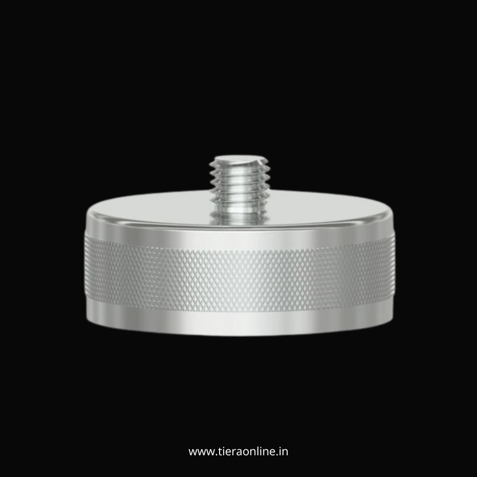
Magnetic Mounting Pad for Vibration Sensor
TIERA's magnetic mount for attaching accelerometers and vibration sensors to metallic surfaces without drilling — the walk-around option this post is about. Ask us for the pull-off and mounted-resonance figures for your surface before you standardise on it.
- Part number
- TMA-101-1A
- Material
- SS 304
- For
- Accelerometers and vibration sensors
- Category
- Accelerometer Mounting Accessories
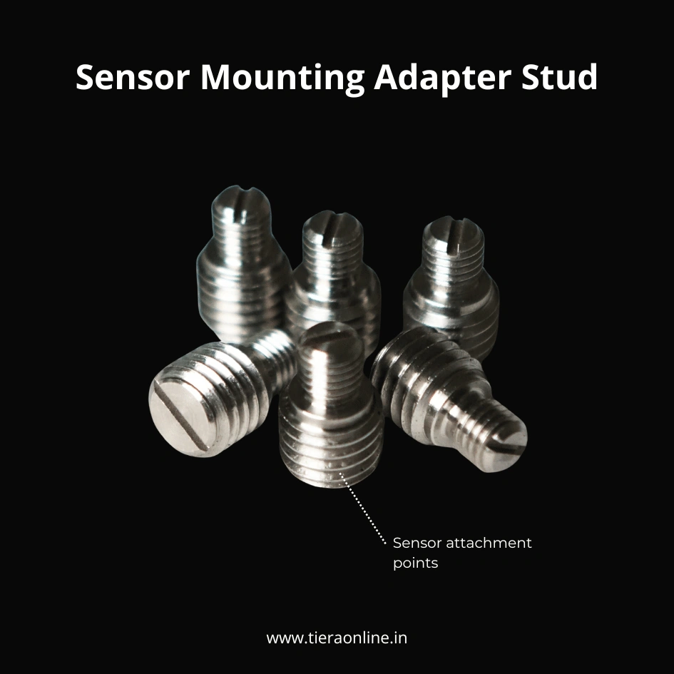
Sensor Mounting Adapter Stud
The reference every magnet is measured against. Screwed into a prepared spot face it gives the stiffest, highest-bandwidth joint available — which is exactly why the mounted-resonance test in the five-test checklist above compares the magnet with a stud-mounted baseline.
- Part number
- TM101-1A
- Material
- SS304
- Function
- Adapter stud for sensor mounting
- Category
- Accelerometer Mounting Accessories
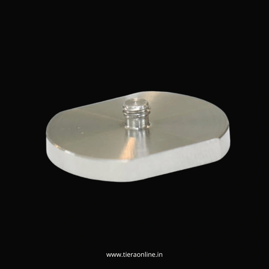
Cementing Pad for Accelerometer Mounting
The answer when the surface itself is the problem — non-magnetic, curved, painted or unmachinable. Bond the pad once, then return to a known flat steel face on every visit instead of a different patch of paint each month.
- Part number
- TAP-101-1-A
- Material
- SS 304
- For
- Accelerometers and vibration sensors
- Category
- Accelerometer Mounting Accessories
From the TIERA store
The kit for this job
What we would actually put in front of someone doing the measurement this post describes — not the whole catalogue.
- Magnetic Mounting Pad for Vibration sensorTMA-101-1A : SS 304 Magnetic Mount for Accelerometers and Vibration Sensors.₹800View →
- Sensor Mounting Adapter StudTM101-1A : TIERA SS304 Adapter Stud for sensor mounting₹260View →
- Cementing pad for Accelerometer mountingTAP-101-1-A : SS 304 Cementing pad for Accelerometers and Vibration sensors₹500View →
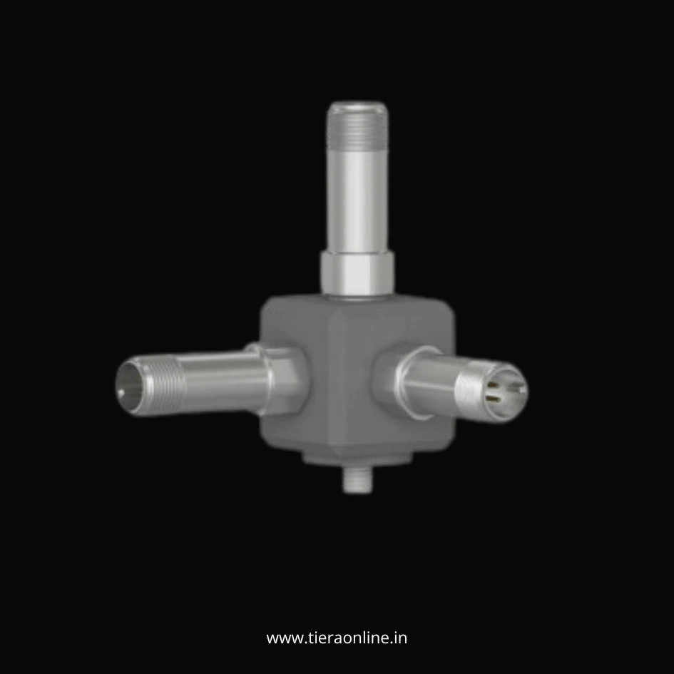 Triaxial Accelerometer Mounting BlockTMB-101-1-A : SS304 Triaxial Mount for Accelerometer Mounting Low Cost Customizable Allows attachment of 3 single axis accelerometers₹2,500View →
Use cases
Where this shows up in the field
Buy the mount for the surface you actually measure on
TIERA supplies the mounting accessories this post is about — an SS304 magnetic mount for route-based collection, an SS304 adapter stud for permanent prepared locations, an SS304 cementing pad for surfaces that are curved, painted or non-magnetic, and an SS304 triaxial mounting block when you need three axes from one point. Each carries its own datasheet in the public TIERA datasheets repository, and each is listed with the parts and cables that go with it.
If you are not sure which geometry your machines need, send us the surfaces: the diameters, the coating, the temperature and the mass of the accelerometer you are using. We would rather answer that question before you buy than explain a missing bearing fault afterwards. Where a figure is not published, ask — and if we cannot give you a measured number for your surface, we will say so rather than quote a brochure.
- TMA-101-1A SS304 magnetic mount for route-based, no-drill attachment
- TM101-1A SS304 adapter stud for permanent, highest-bandwidth locations
- TAP-101-1-A SS304 cementing pad for curved, painted or non-magnetic surfaces
- TMB-101-1-A SS304 triaxial mounting block for three axes from one point
Where this sits on the TIERA learning ladder.
The theory behind this article is covered free, in full, by the TIERA 101 primers: Accelerometer & DAQ Selection 101, Measurement Setup 101. They are self-paced, interactive, and end in an exam and a certificate.
The free primers cover sensors, mounting and measurement setup end to end; TCAT adds examined, instructor-led depth — mounted-resonance checks, surface preparation and defensible survey practice — with proctored examinations that certify competence.
TIERA 101 is a free introductory primer, not an accredited ISO certification, and its hours do not count towards the formal training ISO 18436 requires.