What Actually Changes When the Sensor Gets Hot
Above about 120 °C the amplifier inside an IEPE accelerometer, not the crystal, is what quits — which is why hot work goes back to charge mode. Then the ceramic starts leaking, the low-frequency corner walks up the axis, and the crystal begins generating charge out of temperature alone. Two simulators let you drive all three effects.
The crystal is not what quits first
- The ceiling belongs to the amplifier, not the ceramic. An IEPE unit's electronics are native to −55 °C to +125 °C, and piezoelectric charge mode is the only family left above about 200 °C.
- Above that ceiling the trade is forced on you: take the amplifier out of the housing and what travels down the cable is charge, at gigaohm impedance, through a connector that is about to get hot.
- Every difficulty in the rest of this post is a consequence of that one move.
Ask anyone why an accelerometer has a temperature rating and you will usually hear something about the crystal. It is a reasonable guess and it is normally wrong. A piezoelectric ceramic is a fired oxide; it does not mind 200 °C in the slightest. What minds 200 °C is the silicon sitting three millimetres behind it.
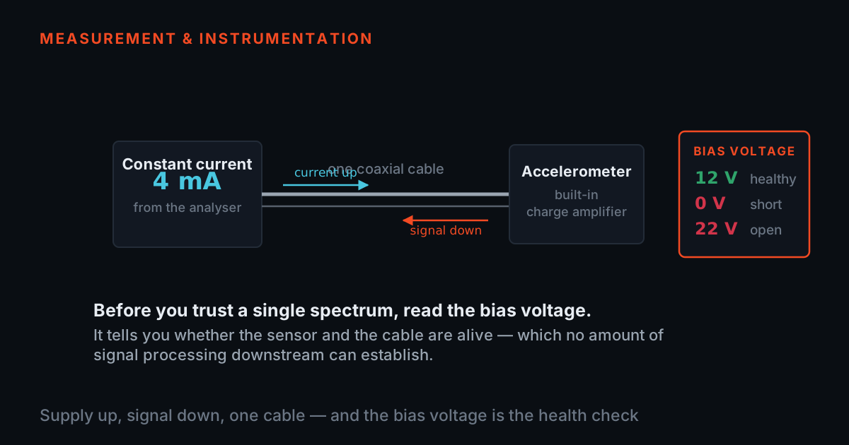
An IEPE accelerometer — the type nearly everyone now uses, sold as ICP®, CCLD, Deltatron® and IsoTron® depending on the maker — puts a small amplifier inside the sensor housing, right at the crystal. That is a genuinely good idea and it is the reason the rest of the measurement chain is so easy: the fragile high-impedance charge signal never leaves the can, and ordinary coax carries a low-impedance voltage back to the rack. We wrote the whole argument out in the signal-conditioning post. But the amplifier has to live where the sensor lives, and semiconductor junctions have opinions about that. Endevco's own thermal-isolation paper puts the native limit of an IEPE unit's electronics at −55 °C to +125 °C — Endevco TP317, "Thermal Isolation of Accelerometers" — and the selection guidance in Endevco TP291, "Accelerometer Selection Based on Applications" names piezoelectric charge-mode as the only family left above about 200 °C.
So the trade is forced on you, not chosen. Above the electronics' ceiling you take the amplifier out of the housing, put it back in the rack where the air conditioning is, and accept the consequence: what now travels down the cable is charge, at an impedance measured in gigaohms, through a connector that is about to get hot. Everything else in this article is a consequence of that one decision.
What the ceramic itself can take, and what "take" means
A piezoelectric ceramic is poled — the domains inside it were aligned once, in a strong field, and the material remembers. Heat is what makes it forget. Above the Curie temperature the aligned structure gives way to a symmetric one, the remnant polarisation goes to zero, and the element is no longer a sensor. That transition is not a slow drift; it is a phase change, and it does not undo itself on the way back down.
Curie temperature is a property of the material family, and the families are far apart. Lead zirconate titanate — ordinary PZT, the workhorse — sits in the region of 200–350 °C depending on the exact composition. Bismuth titanate is up around 600 °C. Lithium niobate is above 1100 °C. Those are textbook material constants, not a specification for any product; the usable rating of a finished sensor is always well below its ceramic's Curie point, because depoling begins as a gradual loss of sensitivity long before the transition proper. A common working rule is to stay under roughly half the Curie temperature in absolute terms and to treat anything above that as a place you calibrate rather than assume.
This is why high-temperature accelerometry is a materials story before it is an electronics story. Endevco TP254, "Accelerometers Developed at High Temperature for Vibration Measurement" reports developing a ceramic with a Curie point above 1750 °F specifically so that accelerometers could be rated to 1400 °F — the ceiling was moved by changing the crystal, not by cooling anything. The same paper reports the price of that move, and it is the subject of the next section: at those temperatures the ceramic's own insulation resistance falls to as little as 10 kΩ.
Insulation resistance falls, and your low end walks up the axis
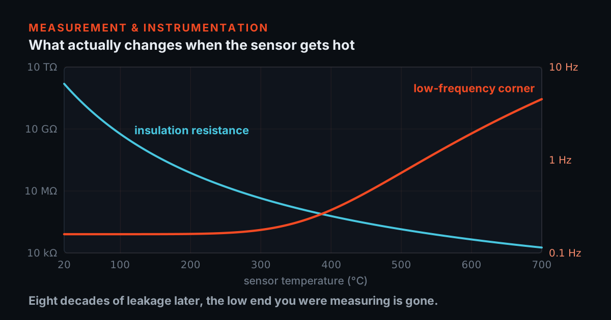
Conduction in an oxide ceramic is thermally activated: charge carriers have to get over an energy barrier, so their number rises exponentially with temperature and the resistance falls the same way. An Arrhenius law captures it — R(T) = R25·exp[(Ea/k)(1/T − 1/T25)] — and with an activation energy of 0.66 eV, a room-temperature value of 1 TΩ falls through 10 GΩ near 100 °C, past 1 MΩ around 400 °C, and reaches the order of 10 kΩ near 760 °C. That last figure is the anchor: it is the order of magnitude TP254 reports for a hot piezoceramic, and it is what sets the activation energy used everywhere on this page. Every other number below follows from it.
Now put that leaking element in front of a charge amplifier. The textbook answer says not to worry: a charge amplifier presents a virtual earth, the input sits at zero volts, so nothing leaks anywhere and the low-frequency corner is set purely by the feedback network, at 1/(2πRfCf). That answer assumes infinite open-loop gain. With a real amplifier of gain A, the virtual earth is only good to within the output divided by A, the leakage resistance Ri appears at the input divided down by A, and the corner becomes
fc = ( 1/Rf + 1/(A·Ri) ) / 2πCf
which is the textbook result whenever A·Ri ≫ Rf, and is something else entirely when it is not. That inequality is the design rule for a hot chain, and it is why a charge amplifier meant for high-temperature work is not the same part as a general-purpose one. It is also, in one line, what TP254 means when it reports a new amplifier circuit developed to tolerate insulation resistance as low as 10 kΩ: what was engineered was the headroom in that inequality.
The simulator below is that arithmetic and nothing else. Drive the temperature and watch the top trace — the leakage — fall through eight decades, then watch the bottom trace — your corner — sit perfectly still until it suddenly does not. Set the open-loop gain low and the corner starts moving around 300 °C; set it high and the ceramic can leak all the way down to kilohms before the amplifier notices. The dashed line is whatever your slowest real tone is, and the shaded region is where that tone stops being a measurement.
Model, stated so you can reproduce every number: insulation resistance follows an Arrhenius law R(T) = R25·exp[(Ea/k)(1/T − 1/T25)] with Ea = 0.66 eV and R25 = 1 TΩ; the charge amplifier has Rf = 1 GΩ and Cf = 1 nF (its own corner, 0.159 Hz) and a finite open-loop gain A, giving a system corner fc = (1/Rf + 1/(A·Ri)) / 2πCf. These are physically motivated orders of magnitude for a piezoceramic and a general-purpose charge amplifier — not a specification for any sensor, ours or anyone else’s.
The other thing a hot crystal does: it makes charge out of temperature
- A poled ceramic is also pyroelectric: change its temperature and charge appears on the electrodes with no mechanical input at all. The charge amplifier cannot tell the difference.
- The envelope arithmetic is brutal — about 8,500 pC per kelvin on a 6 mm disc, which against a 10 pC/g sensitivity is 850 g per kelvin if the chain passed DC.
- It does not pass DC, which is the only reason anyone measures anything near a furnace: a temperature step becomes a decaying spike, and what survives a ramp is the ramp rate times the chain's time constant.
- The number to ask for is the sensor's measured temperature-transient sensitivity in g per kelvin. Shear designs cancel much of the primary output; compression designs take the full hit.
Every poled piezoelectric ceramic is also pyroelectric. Change its temperature and the remnant polarisation changes with it, which pushes charge onto the electrodes — no force, no acceleration, no mechanical input of any kind. The charge amplifier cannot tell the difference. It was built to integrate charge, and charge is exactly what it has been given.
The magnitude is worth doing on the back of an envelope, because it is the part people underestimate. A PZT-type ceramic has a pyroelectric coefficient of order 3 × 10⁻⁴ C m⁻² K⁻¹. Put that on a 6 mm disc — an area of 2.8 × 10⁻⁵ m² — and one kelvin produces about 8.5 nC, which is 8500 pC. Against a charge sensitivity of 10 pC/g that is 850 g per kelvin, if the chain passed DC. It does not, which is the only reason anybody can measure anything at all near a furnace: the chain's own high pass turns a temperature step into a decaying spike, and what survives from a temperature ramp is the ramp rate multiplied by the chain's time constant.
That is the honest form of the effect, and it is why the number that matters is not the raw ceramic figure but the sensor's measured temperature-transient sensitivity, in g per kelvin, which is a line on a real datasheet. Two things move it. Geometry: a compression-design element has its electrodes normal to the thermal gradient coming up through the base, and takes the full primary pyroelectric hit, whereas a shear design orients the element so that much of the primary output cancels — Endevco TP250, "Accelerometer Characteristics Used in Transient Motion and Nuclear Applications" separates the primary, secondary and tertiary pyroelectric contributions by exactly this distinction. And thermal mass: anything that slows the gradient reaching the element reduces the ramp rate the ceramic actually experiences, which is what a thermal isolator is for.
The second simulator lets you drive all of it. Set a ramp rate, set a transient sensitivity — put your own datasheet figure in, that is what the slider is for — set the vibration you are trying to measure underneath it, and then try to filter your way out of the problem. You will find you can, and you will find what it costs.
Model, stated so you can reproduce every number: pyroelectric charge is proportional to temperature CHANGE, so the apparent acceleration is (transient sensitivity) × ΔT; the ramp runs from 5 s to 15 s and then holds; the chain’s own first-order corner is fixed at 0.16 Hz and the extra high pass is first-order at the corner you set; the chain is taken to run out of range at ±50 g. Transient sensitivity is a slider, not a constant we picked for you — put your own sensor’s datasheet figure in and read the answer for your machine.
Cable and connector: the leakage you add yourself
- The insulation resistance in the corner equation is the ceramic in parallel with the cable dielectric, the connector, and any film of moisture, oil or conductive dust. Parallel resistances add as conductances, so the worst one wins.
- A 1 TΩ crystal behind a contaminated connector at 10 MΩ is a 10 MΩ chain — set the first simulator to wherever the ceramic reaches 10 MΩ on its own and it will show you what that does to your corner.
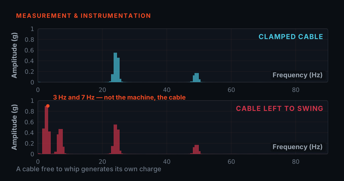
- Charge mode has a cable problem IEPE does not: flexing a coax generates charge directly, and the amplifier integrates triboelectric noise as happily as anything else.
The insulation resistance in the corner equation is not the ceramic's alone. It is the ceramic in parallel with the cable dielectric, in parallel with the connector, in parallel with whatever film of moisture, oil or conductive dust has settled on the insulator faces. Parallel resistances add as conductances, so the total is always dominated by the worst one. A 1 TΩ crystal behind a contaminated connector at 10 MΩ is a 10 MΩ chain, and the simulator above will tell you exactly what that does to your corner if you set the temperature to wherever the ceramic reaches 10 MΩ on its own.
This is why the hot run of a charge-mode installation uses hard-line cable — a metal-sheathed, mineral-insulated assembly, sealed and often integral to the sensor — rather than a polymer-jacketed coax. Compacted mineral insulation keeps its resistance where organic dielectrics have already given up, the sheath is a continuous shield, and there is no organic material left to outgas or char. TP254 names metal-sheathed cabling as one of the three things that had to be developed alongside the ceramic and the amplifier, and it is the one most often left out of a retrofit.
Charge mode has a second cable problem that IEPE simply does not have: because the signal is a charge on a very high impedance, the cable itself is part of the measurement. Flexing a coaxial cable separates the dielectric from the shield and generates charge directly — triboelectric noise — and the amplifier integrates that as happily as it integrates anything else. Endevco TP324, "Practical Considerations of Accelerometer Noise" makes the point plainly: use treated low-noise cable, keep it short, clamp it so it cannot flap, and keep the connectors clean and dry. On a hot machine, "clean and dry" is a maintenance instruction with a service interval, not a one-off at commissioning. Our cable post covers the construction and the tests; everything there still applies, only with less margin.
- Specify the hot run as hard-line, metal-sheathed, mineral-insulated cable, sealed and ideally integral to the sensor.
- Use treated low-noise cable on any charge-mode run, keep it short, and clamp it so it cannot flap.
- Keep the connectors clean and dry, and put that inspection on a service interval.
- Treat the connector and cable as part of the insulation resistance when you work the corner equation.
- Retrofit a polymer-jacketed coax onto a hot run because it was what was on the shelf.
- Leave a charge-mode cable loose where it can flex — the triboelectric charge lands straight in your measurement.
- Sign off "clean and dry" once at commissioning and never look again.
- Blame the ceramic for a walked corner before you have checked what is in parallel with it.
Sensitivity drift: the certificate was written at 25 °C
The number on your calibration certificate was measured on a shaker in a room at about 23 °C, and it is a true number about the sensor at 23 °C. The piezoelectric coefficients of a ceramic are not constants; they climb with temperature as the material softens toward its transition, then collapse through it. So the sensitivity you are operating at is not the sensitivity you were sold, and the gap grows with the temperature you are working at.
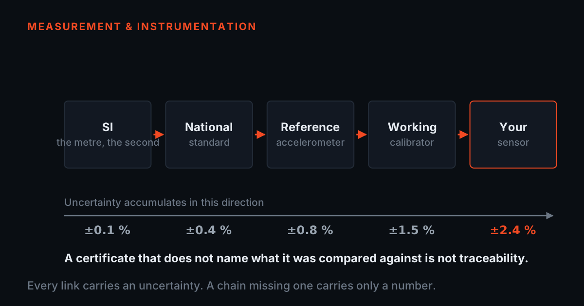
The honest way to handle this has three steps and only the first one is free. First, get the manufacturer's sensitivity-versus-temperature curve for the model — it exists, it is a normal thing to ask for, and it is usually a deviation plot in percent against a 23 °C reference. Second, decide whether you are going to correct for it or carry it as uncertainty; both are defensible, and stating which you did is what makes the reading defensible. Third, if the measurement genuinely matters at temperature, calibrate at temperature — an oven-and-shaker calibration is a real service and it is the only thing that closes the loop. Nothing about the traceability chain changes here; what changes is that the environment has become a calibration parameter instead of a footnote.
One further point, and it is the one that gets missed in condition monitoring: drift matters far less for trending than for absolute readings, but only if the temperature is stable. A sensor on a machine that runs hot and steady is trending against a constant, if unknown, sensitivity — perfectly usable. The same sensor on a machine that cycles is trending against a sensitivity that moves with load, and the trend will show a fault that is really a duty cycle. If you take one thing from this section, take that one: log the sensor's temperature alongside the vibration, and look at them together before you believe a trend.
Thermal isolation buys temperature and spends bandwidth
- An isolator is a compliance inserted in series with the stud, so the mounted resonance drops and the usable ceiling drops with it at the same one-third-of-resonance rule.
- TP317 quantifies its own case as linear out to about 4 kHz with the isolator fitted. Whatever the number is for your stack, the shape of the trade is fixed.
- If you were there to catch early bearing tones, that may be the wrong trade — and the answer is then a charge-mode sensor that can sit on the surface, not a better isolator.
The other way to survive a hot surface is not to sit on it. A thermal isolator — a low-conductivity disc bolted between the machine and the sensor base — drops the sensor's steady-state temperature well below the surface's, which can bring an otherwise unusable sensor back inside its rating. TP317 reports exactly that experiment: an IEPE triaxial unit on a 175 °C hot plate stabilising far below the plate and holding that reduced temperature for the duration of the test.
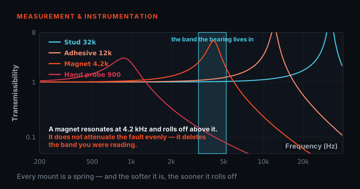
It is not free, and the cost is entirely predictable from mechanics we have already worked through elsewhere. The mounting joint is a spring, and the accelerometer is a mass on it; the mounted resonance is set by the stiffness of the softest layer in the stack. Insert a polymer disc and you have inserted a compliance in series with a stud, and the mounted resonance drops accordingly — which drags the usable ceiling down with it, at the same one-third-of-resonance rule of thumb our mounting simulator is built around. TP317 quantifies its own case as a linear response holding out to about 4 kHz with the isolator fitted. Whatever the number is for your stack, the shape of the trade is fixed: you are exchanging high-frequency bandwidth for temperature margin, and if you were there to catch early bearing tones, that may be the wrong trade.
The same logic applies to the cheaper version — a standoff or a length of stud, which works by the same physics and is even softer. It also applies to the honest version of the question: if the isolator costs you the band the fault lives in, the answer is not a better isolator, it is a charge-mode sensor that can sit on the surface.
A short procedure that survives contact with a hot machine
Start with the temperature at the mounting face, measured, not assumed, and measured at the worst point of the duty cycle rather than at a convenient moment. If it is under about 120 °C, use IEPE and stop reading. If it is over it, you are in charge mode and the rest of this list applies.
Get the sensor's temperature-transient sensitivity in g per kelvin, and the ramp rate the machine actually produces on start-up or on a soot-blow. Multiply them, put the result into the second simulator, and find out before you install whether the vibration you want will be visible at all. This is the single check that most often changes a design, and it takes two minutes.
Check the corner equation against your charge amplifier's real open-loop gain and the sensor's insulation resistance at operating temperature — the first simulator does this for you. If the answer walks your corner into the band you care about, you need a different amplifier, not a different sensor. Then specify the hot run as hard-line or mineral-insulated cable, with a sealed connector, and write the connector inspection into the maintenance schedule rather than hoping.
Finally, log temperature alongside vibration on every hot point, and get the sensitivity-versus-temperature curve into the same place your analyst reads the trend. A hot machine gives you two signals whether you record the second one or not; you may as well have it.
If you want the fundamentals under all of this — how a piezoelectric sensor works, what IEPE is doing, sensitivity, sampling, and measurement setup including mounting and cabling — TIERA publishes free primers at 101.tieraonline.in: Accelerometer & DAQ Selection 101 and Measurement Setup 101 cover exactly this ground. TIERA 101 is a free primer series, not an accredited ISO certification. For teams that need formally examined competence, the TCAT programme (see /services) goes deeper, with proctored examinations conducted at exams.tieraonline.in.
From the TIERA store
The kit for this job
What we would actually put in front of someone doing the measurement this post describes — not the whole catalogue.
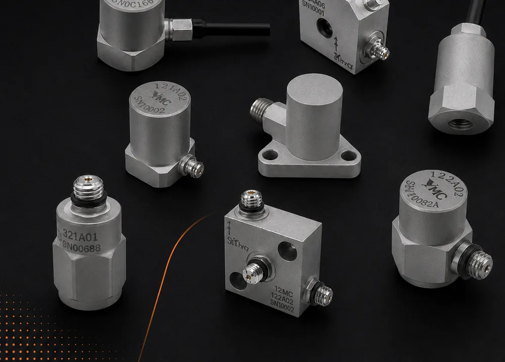 High Temperature AccelerometerYMC Series High Temperature Accelerometers use high-impedance charge output mode so the sensing element can be taken far above the limit of built-in electronics — up to +482 °C on the Inconel-housed 272A H models.Request priceView →
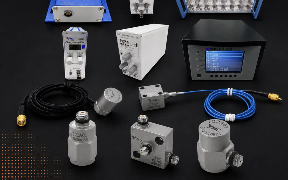 Charge AmplifiersYMC 81 series charge amplifiers convert the charge output by a piezoelectric sensor into a proportional voltage, used as the input variable for analysis systems and digitised by an A/D converter if required.Request priceView →
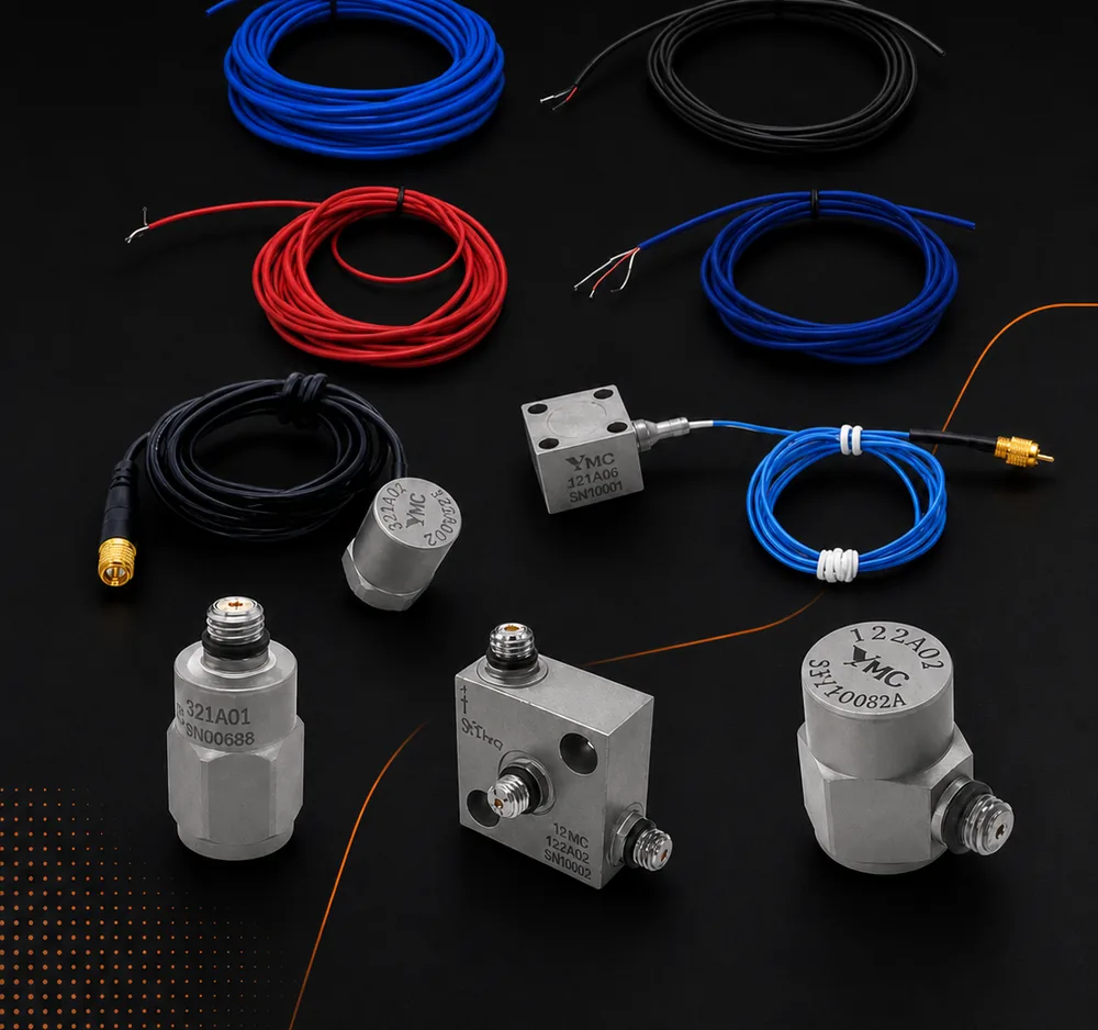 CablesYMC supplies the full cable range behind a piezoelectric measurement chain — low-noise charge cables, coaxial IEPE cables, multi-conductor industrial and triaxial cables, waterproof and high-temperature types, and spiral cables for handheld devices.Request priceView →
Use cases
Where this shows up in the field
Hot points need a different chain, not a braver sensor
TIERA supplies the charge-mode side of the measurement chain as well as the IEPE side: high-temperature charge-output accelerometers, multi-channel charge amplifiers with selectable high-pass and low-pass filtering, and the low-noise and high-temperature cable types a charge signal needs to survive the run back to the rack. Specifications for every one of them are on the product pages — this post deliberately prints none of them, because the whole argument here is that the right numbers are the ones for your machine and your temperature, not a headline rating.
If you are unsure whether a point needs charge mode at all, the two simulators above will usually settle it in five minutes. If they do not, tell us the surface temperature, the ramp rate on start-up, and the lowest frequency you need to trust, and we will work the same arithmetic against real parts.
- Charge-output accelerometers for surfaces past the limit of built-in electronics
- Charge amplifiers with the gain and filtering to keep the corner where you put it
- Low-noise and high-temperature cable types, with the insulation and capacitance figures published
- An engineering answer on whether a given point needs charge mode, before anything is bought
Where this sits on the TIERA learning ladder.
The theory behind this article is covered free, in full, by the TIERA 101 primers: Accelerometer & DAQ Selection 101, Measurement Setup 101. They are self-paced, interactive, and end in an exam and a certificate.
TCAT adds examined, instructor-led depth on the measurement chain — sensor technology choice, environmental limits, and defensible survey practice on machines that do not sit at room temperature — with proctored exams that certify competence; the free primers explain, TCAT verifies.
TIERA 101 is a free introductory primer, not an accredited ISO certification, and its hours do not count towards the formal training ISO 18436 requires.