The Cable Is Part of the Measurement
A vibration cable carries a signal of a few millivolts. Flex the wrong cable and it generates its own charge, burying the bearing fault you bought the sensor to find. What makes a cable good, how cable quality is tested, and why the cheapest cable is the expensive one.
A cable is not an accessory — it is inside the measurement
- Between the sensing element and the first amplifier the cable is the signal path — whatever it adds arrives looking like acceleration, and nothing downstream knows which volts came from the bearing.
- Charge-mode and IEPE fail differently: a charge-mode sensor pushes a raw charge down a very high-impedance line and must use treated cable, while an IEPE sensor's built-in amplifier makes it far more tolerant — not immune.
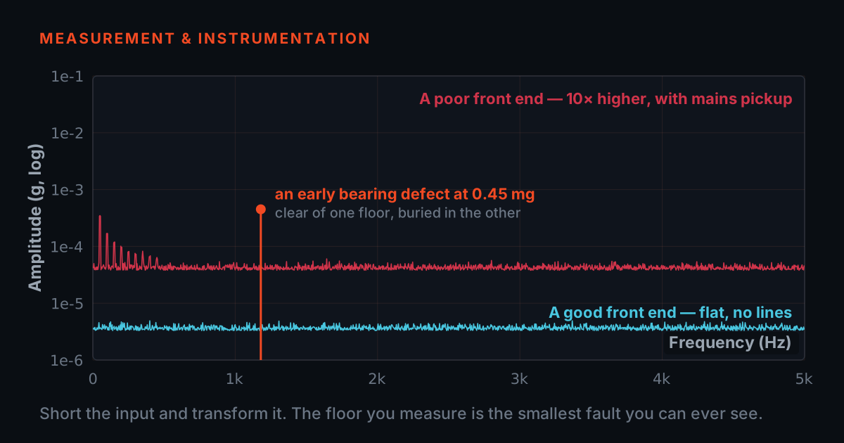
Take a bearing fault that is worth finding early: an outer-race defect showing up as a 10 mg line in the acceleration spectrum. On a 100 mV/g accelerometer, 10 mg is one millivolt. On a charge-mode accelerometer of 10 pC/g it is a tenth of a picocoulomb. That is the size of the thing travelling down the cable — smaller than the interference radiated by a contactor closing two metres away.
This is why a vibration cable belongs on the same list as the sensor and the analyser rather than on the list with cable ties and mounting screws. Between the sensing element and the first amplifier, the cable is the signal path, and anything it adds — noise it generates itself, noise it lets in from outside, bandwidth it takes away — is indistinguishable from machine vibration by the time the analyser sees it. There is no software step later that can separate the two, because nothing downstream knows which volts came from the bearing.
Two electrical arrangements are common, and they fail differently. A charge-mode accelerometer sends a raw charge down the cable to a remote charge amplifier: extremely high impedance, extremely vulnerable, and it must use a treated low-noise cable. An ICP/IEPE sensor has a miniature amplifier built in and runs on a constant current — typically 4 mA at up to about 24 V — sent up the same two wires that carry the signal back. IEPE is far more tolerant, which is why it dominates industrial work, but 'more tolerant' is not 'immune': the same millivolt-scale signal still has to survive the trip.
Triboelectric noise: how flexing a cable invents a signal
- The dominant corruption is made inside the cable, by the cable's own motion — not picked up from outside.
- It lands low in frequency and in bursts, which is the same place and the same shape as running speed, its harmonics, and an early bearing defect.
- The only difference between a treated and an untreated cable is a graphite layer under the braid that shorts the separated charge away. It is invisible from the outside, and the two cables can cost very different amounts.
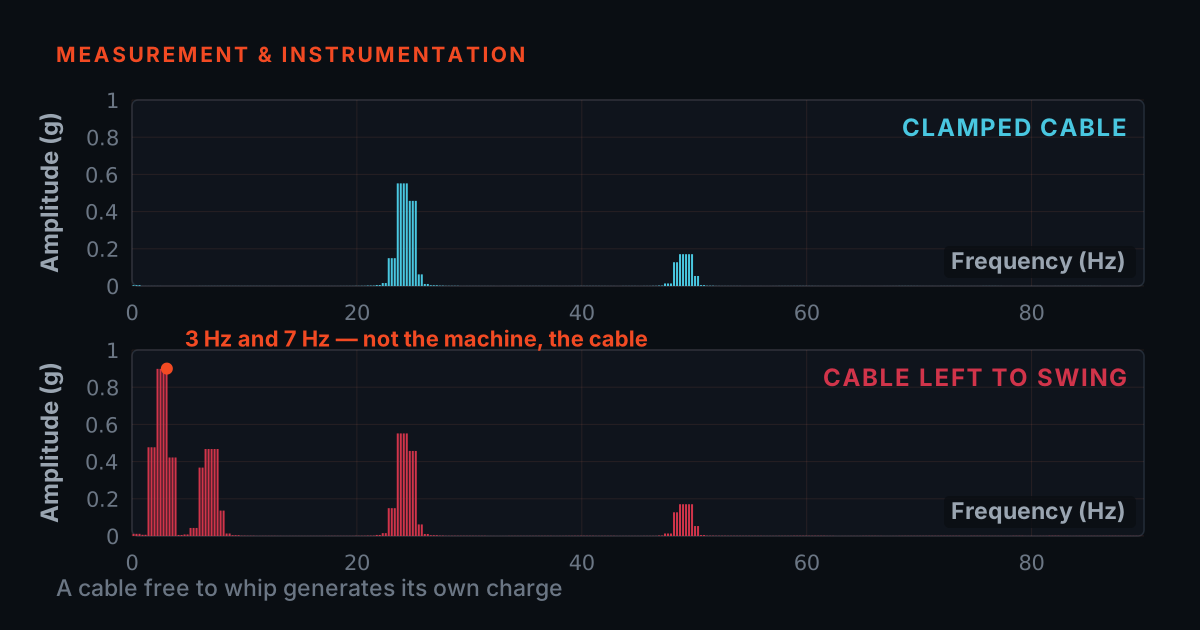
The dominant reason a cheap cable corrupts vibration data has nothing to do with interference from outside. It is generated inside the cable, by the cable, when it moves. Rub two dissimilar insulating materials together and charge transfers between them — the same effect that makes a balloon stick to a wall. Inside a coaxial cable, the materials in contact are the dielectric and the shield braid pressing on it. Bend or shake the cable and the braid slips microscopically against the dielectric, separates from it in places, and presses back in others. Charge moves. That charge appears at the input of the amplifier, and it is completely indistinguishable from charge produced by the accelerometer.
This is triboelectric noise. Three of its properties make it especially destructive in vibration work. It is driven by cable motion, so it is worst exactly where the cable is attached to a vibrating machine. It is low in frequency — cable flexing happens at a few hertz to a few tens of hertz — which is precisely the region where running speed, its harmonics and the bearing defect frequencies of slow machines live. And it is burst-like rather than steady, so it does not look like a clean noise floor you could recognise and dismiss; it looks like transients, which is exactly what a bearing fault also looks like.
A treated low-noise cable attacks the mechanism directly. During manufacture a thin conductive or semiconducting layer — commonly a graphite or carbon-loaded coating — is applied over the dielectric, under the braid. The layer is electrically continuous with the shield, so any charge that separation would have produced is short-circuited away before it can reach the centre conductor. It also lubricates the interface, reducing the stick-slip motion in the first place. That layer is the entire difference between a cable that stays quiet on a running machine and one that does not, and it is invisible from the outside. The two cables can look identical, use the same connectors and cost very different amounts.
One honest qualification: an untreated cable is not noisy when it is lying still. Bench-test a cheap cable on a static setup and it will pass. It only misbehaves when it is doing the job you bought it for, clamped to a machine that vibrates.
Try it: the cable noise bench
The bench below runs a synthetic measurement on a machine turning at 1500 rpm (25 Hz) with an outer-race bearing defect producing a 10 mg line at 87.5 Hz and two harmonics above it. The top trace is the time waveform the DAQ sees; the bottom is its spectrum. Everything the machine does stays fixed. The only things you change are the cable and what is happening to it.
Start with the low-noise cable, a full foil-plus-braid shield, five metres, no flexing: the bearing line stands well clear of the floor. Now switch the cable type to standard untreated coax and drag the flex slider up — or press 'Flex the cable' to whip it once. Watch the low-frequency grass rise under the signal and the bearing line disappear into it. Switch back to low-noise without touching anything else and it returns. Then set the shield to a thin partial screen, turn on the nearby drive, and stretch the run out to forty metres: a different mechanism, the same outcome.
This is a teaching model, not a measurement. The mechanisms are qualitatively right — triboelectric noise is low-frequency and burst-like and scales with cable motion; poor screening lets mains and drive harmonics plus broadband hash onto the conductor — but the constants were chosen so the effect is visible on a small screen. Do not read absolute numbers off it.
Indicative teaching model, not a measurement. Noise mechanisms are qualitatively representative; magnitudes are chosen for legibility on screen. Real cable noise depends on the construction, the sensor, the input impedance and how the cable is routed and clamped.
Shielding, coverage and where the ground goes
- Coverage decides how much gets in: 40 to 60 percent for a light spiral screen, 85 to 95 for a good braid, near-total for foil-plus-braid.
- Drive noise arrives in two forms — discrete lines that look like machine orders, and broadband hash. The discrete lines are the ones that cost an hour of a review meeting.
Triboelectric noise is made inside the cable. The other family of problems arrives from outside, and the shield is what stops it. A shield works by giving interference a low-impedance path to ground instead of onto the signal conductor, and how well it does that depends on how completely it wraps the conductor. Braid coverage is quoted as a percentage: a light spiral screen might manage 40 to 60 percent, a good braid 85 to 95 percent, and a foil-plus-braid construction approaches full coverage — foil for the high frequencies where gaps in a braid start to look like windows, braid for mechanical robustness and low DC resistance.
Coverage stops being an academic number the moment you route a cable near a variable-speed drive. A drive switches large currents thousands of times a second with very fast edges, and those edges radiate. What reaches the analyser through an incomplete screen is a mixture of discrete lines related to the supply and switching frequencies and broadband hash across the whole spectrum. Both are dangerous in a different way from triboelectric noise: the discrete lines look like machine orders, and a line at 100 Hz sitting a few hertz from a real bearing frequency will be argued about in a review meeting for an hour. If the cable must run near a drive, near the motor terminal box, or parallel to power cabling in the same tray, screening quality is the specification that matters most.
Then there is grounding, which defeats more good cable than poor shielding does. If the shield is bonded to ground at the sensor end — because the accelerometer case is bolted to the machine frame — and also at the analyser end through the instrument's chassis, the shield becomes one side of a loop. Any difference in ground potential between the machine and the instrument drives a current around that loop, and that current appears in the measurement, usually as a strong mains-frequency component. The remedy is single-point grounding: bond the shield at one end only, conventionally the instrument end, and keep the sensor electrically isolated from the machine using an isolated stud or an insulating mounting pad. If a persistent 50 Hz line appears and moves when you touch the instrument earth, you are looking at a ground loop, not at the machine.
Cable length, capacitance and the frequency you can still reach
- For an IEPE sensor, cable capacitance sets the highest frequency you can measure without slew-rate distortion. Length is a bandwidth specification, not a logistics detail.
- The fix for a long run is more supply current — which is why 10 and 20 mA options exist — and the price is more self-heating in the sensor.
A cable has capacitance between the conductor and the shield, typically in the region of 30 to 100 picofarads per metre depending on the construction. For an IEPE sensor this is not a detail — it sets the highest frequency you can measure without distortion. The sensor's internal amplifier has only the constant current from the supply, minus its own bias current, available to charge and discharge that capacitance. The larger the swing you ask for and the more capacitance you hang on the output, the sooner the amplifier runs out of current and the waveform starts to distort — the classic slew-rate limit.
The published relationship is simple enough to keep in your head. With the constant current and the sensor's bias current in milliamps, the total cable capacitance in picofarads and the largest signal you expect in volts peak, the usable upper frequency is roughly f = 10⁹ × (I_supply − I_bias) / (2π × C × V). At 4 mA supply, 1 mA bias, 5 V peak and 10 m of 100 pF/m cable that comes out at about 95 kHz — nowhere near a limitation. Stretch the same setup to 100 m and it falls to about 9.5 kHz, which now sits inside the band you would use for bearing work. The fix when you need both length and bandwidth is more current: many supplies offer 10 or 20 mA precisely for long runs.
Three practical notes. The relationship is indicative and assumes the standard slew-limited model, so treat the answer as an order of magnitude and use the sensor's own bias current from its datasheet rather than the 1 mA assumed here. It is driven by the largest voltage the sensor will actually produce, so a high-sensitivity sensor on a rough machine hits the limit sooner than the same cable on a quiet one. And more current means more self-heating in the sensor, which is why 4 mA remains the sensible default for short runs.
Indicative. Uses the standard published IEPE relationship f = 10^9 (Ic - Ib) / (2π C V), assuming a 1 mA sensor bias current - take the real value from your sensor datasheet. Cable capacitance per metre varies by construction; connectors and junction boxes add more.
Connectors and strain relief: where cables actually die
Cables rarely fail in the middle. They fail within the last few centimetres, at the transition from flexible cable into rigid connector, because that is where the bending stress concentrates and where the conductor, the shield and the moulding all have to change from one thing into another. Every time the cable is pulled, twisted at the plug, or left hanging by its own weight from a sensor, that joint takes the load.
The connectors themselves are chosen for the job. The 10-32 microdot is the miniature coaxial standard on small accelerometers — a tiny threaded coaxial connector, sensitive to over-torque and to side loads, and best treated as a precision item rather than something to tighten with pliers. BNC is the bayonet coaxial connector on the instrument side: quick, positive, and easy to check because you can feel the quarter-turn lock engage. The two-pin circular MIL connector, such as the Amphenol type TIERA fits on its accelerometer and armored cables, is the rugged industrial choice — a screwed or bayonet shell that survives being dragged around a plant and keeps its contact under vibration.
The construction difference that matters is moulded versus field-assembled. In a moulded termination the joint is overmoulded in one piece with the jacket, so the strain relief is part of the cable and the bend is spread over a long, tapering boot. In an assembled connector the joint is made by hand inside a shell, and its life depends entirely on how the clamp and boot were fitted. A field-assembled connector is repairable, which matters on a long permanent run; a moulded one is more reliable, which matters on a walk-around route cable that gets coiled and uncoiled every day.
Coiled cables exist for the same reason: they take the length changes into the coil rather than into the joint, and they keep a walk-around measurement tidy without a metre of slack dragging on the floor. The trade is that a coil is always under some tension when extended, so check the extension range and do not use the cable at the end of its stretch.
Heat, oil, abrasion and flex life
The environment sets the jacket and, with it, most of the cable's service life. Temperature rating is the first filter: a cable clipped to a pump casing sees ambient, but one routed past a steam line or bolted near a gearbox that runs hot sees far more, and a jacket used above its rating goes hard, then cracks at every bend. Oil and coolant are the second. Many general-purpose jackets swell and soften in mineral oil or cutting fluid, and a softened jacket no longer holds the braid in place — which quietly brings back the triboelectric problem the low-noise treatment was there to solve.
Abrasion and crush matter wherever a cable is dragged, walked on, or run through a cable tray with sharp edges. This is what an armored construction is for: a stainless-steel outer over the shielded cable takes the mechanical damage so the signal path does not, at the cost of stiffness and weight. TIERA's CA-103 cables are built this way, with a stainless-steel outer armor over a tinned copper braid, two-core twisted shielded cable, for exactly these installations.
Flex life is the specification people forget and then discover. A cable clamped to a machine is not bent once — it is bent a few million times, at machine frequency, for years. Repeated bending work-hardens strands until they break one at a time, and a cable with a partially broken shield or a few broken strands in a stranded conductor does not fail cleanly; it becomes intermittent and noisy, which is far harder to diagnose than an open circuit. Two habits prevent most of it: leave a service loop so the cable is never taut and the bend radius never falls below the manufacturer's minimum, and clamp the cable to the machine close to the sensor so that the machine's motion moves cable and sensor together instead of whipping the free length.
- Leave a service loop, so the cable is never taut and never bends tighter than the manufacturer's minimum radius.
- Clamp the cable to the machine close to the sensor, so cable and sensor move together instead of the free length whipping.
- Match the jacket to the temperature the cable will actually see, not to the ambient you felt on a cool morning.
- Specify an armored construction wherever the cable is dragged, walked on, or run through a sharp-edged tray.
- Route a general-purpose jacket past a steam line or a hot gearbox and expect it to stay flexible.
- Leave a cable sitting in mineral oil or cutting fluid — a softened jacket lets the braid move again, and the triboelectric problem comes straight back.
- Hang a sensor on its own cable, or take up slack by pulling at the plug.
- Write off an intermittent, noisy channel as a sensor fault before you have looked at how that cable has been bent.
Testing a cable, part one: the electrical checks
This is the part of buying a cable that most people skip, and it is the part that separates a specification from a promise. All of the following are standard practice in cable manufacture and none of them require exotic equipment. What matters is whether the supplier performs them, on what sample, and against what limits — so each test below is written as a question you can put to a supplier.
Continuity and DC resistance. The simplest check: every conductor connected end to end, correctly mapped to the right pin, and no short between conductor and shield. Beyond a buzzer test, measure the loop resistance — ideally four-wire, since a couple of ohms of test-lead resistance swamps the result — and compare it with what the conductor gauge and length predict. A reading well above prediction means a poor crimp or solder joint at a connector, which is a joint that will go intermittent later. Ask: what is the measured loop resistance for this length, and what limit do you apply?
Insulation resistance. Apply a DC test voltage between the conductor and the shield and measure the leakage. A healthy instrumentation cable reads in gigaohms; a value in megaohms means moisture ingress, a damaged dielectric or contamination in a connector, all of which show up later as drift and low-frequency noise. The test voltage must be appropriate to the cable's rating, so ask both numbers together: what voltage do you test at, and what minimum do you accept?
Capacitance per metre. Measure conductor-to-shield capacitance on an LCR bridge at a stated frequency, typically 1 kHz, and divide by the length. This is the number that feeds straight into the IEPE bandwidth calculation above, and it is also a good integrity check: a capacitance well away from the nominal value means the geometry is not what it should be. Ask: what is the capacitance per metre and its tolerance?
Shield continuity and bonding. The braid must be continuous end to end and actually bonded to the connector shell in the way the design intends — including, on a single-point-ground design, deliberately not bonded at one end. A shield that is continuous but connected to nothing is decoration. Ask: how is the shield terminated at each end, and is that documented on the drawing?
Testing a cable, part two: mechanical, and the one test that decides it
- One test separates a cable labelled low-noise from a cable that is: record the noise floor with everything still, then record it again while the cable is flexed, in the same chain.
- Ask for it as a spectrum, over a stated band, with the sensor, supply current, cable length and flexing motion named. A single number with no conditions attached tells you nothing.
Connector pull-off and strain relief. Fix the connector, apply a stated axial force to the cable, hold it for a stated time, then repeat the continuity, resistance and insulation checks. Nothing should change and the connector should not rotate or pull out of its boot. The number itself matters less than the fact that a number exists: a supplier who can tell you the force and the duration has a procedure, and a supplier who cannot, does not. Ask: what force, for how long, and what do you re-measure afterwards?
Flex and bend cycling. Clamp one end, bend the cable over a mandrel of a defined radius through a defined angle, and cycle it a defined number of times — this is how flex life is demonstrated rather than asserted. Afterwards, repeat the electrical checks: what you are looking for is a rise in loop resistance from broken strands, a fall in insulation resistance from a cracked dielectric, or a shield that has lost continuity. Ask: what bend radius, what angle, how many cycles, and what did you measure afterwards?
And then the decisive one: low-noise verification under flexing. This is the test that separates a cable that says 'low-noise' on the label from a cable that is. Connect the cable in the real chain — an accelerometer or a capacitive dummy that mimics the source impedance, the IEPE supply or charge amplifier that will actually be used, and an analyser. Record the noise floor with everything perfectly still: that is the instrument's own floor plus the sensor's. Then flex the cable through a defined motion — tap it, whip it, bend it over a former, or shake it on a shaker — and record again. A treated low-noise cable shows a small rise. An untreated cable shows a large low-frequency rise, often with visible bursts, and the difference between the two records is exactly the effect you were driving in the simulator above.
The result should be reported the way any noise floor is reported: as a spectrum, over a stated frequency band, in engineering units — microgee per root hertz, or millig RMS over the band — with the sensor, the supply current, the cable length and the flexing motion all stated, because every one of those changes the answer. A single number with no conditions attached tells you nothing. Ask for the plot: static floor and flexed floor, on the same axes.
Two further checks are worth having on the list. Length and marking, so that the cable in the store is the cable on the drawing and its part number, length and pin-out are legible on the cable itself years later. And a pin-out verification per connector type, because a cable that is electrically perfect and wired signal-to-ground is a cable that will damage nothing and measure nothing.
What to ask before you buy
The whole article reduces to a short list you can put in an email. Is the cable low-noise treated, and what is the treatment? What is the shield construction and its coverage percentage? What is the capacitance per metre? What are the temperature rating and the jacket material, and is it rated for oil or coolant exposure? What is the minimum bend radius, and is there a flex-cycle figure behind it? How is the strain relief made — moulded or assembled — and what pull-off force has been demonstrated? How is the shield terminated at each end? And, the one that will tell you the most about the supplier: can you show me the noise floor of this cable measured static and measured while flexed?
None of those questions are unreasonable, and none of them require the supplier to reveal anything proprietary. What they do is separate suppliers who understand that a cable is a measurement component from suppliers who treat it as a length of wire with plugs on the ends. If the answer to most of the list is a shrug, you have learned what you needed to know — and you have learned it before the cable is clamped to a machine rather than after six months of data you cannot trust.
The false economy, in engineering terms
- The cable is a low single-digit percentage of a measurement channel — roughly ₹1,300 to ₹2,600 against ₹15,000 to ₹1.21 lakh for the sensor alone, before DAQ, software and analyst time.
- The cost nobody prices is irreproducibility: cable noise depends on how the cable happened to be routed that day, so two surveys of one healthy machine disagree and the trend — the most valuable thing the programme owns — turns to noise.
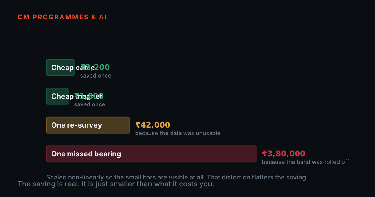
Set the money out honestly. In TIERA's own store, accelerometer cables list between roughly ₹1,300 and ₹2,600, while the accelerometers they feed list from about ₹15,000 for a multipurpose IEPE unit to ₹1.21 lakh for a miniature triaxial, and the DAQ, the software and the analyst's time sit on top of that. The cable is a low single-digit percentage of the cost of a measurement channel. Saving half of it saves a rounding error.
Now set out what the saving buys you. The simulator earlier made the mechanism concrete: an untreated cable clamped to a running machine raises the low-frequency noise floor to the point where a 10 mg bearing line stops being distinguishable. Two failure modes follow, and both are expensive. The first is a missed fault — the defect frequency is present in the machine and absent from your report, so the bearing runs on to secondary damage, and the programme that was supposed to catch it looks like it does not work. The second is a false alarm — triboelectric bursts look like impacts, and impacts look like a bearing, so somebody opens a healthy machine, finds nothing, and trusts the next alarm less. A condition-monitoring programme survives missed faults for a while. It does not survive its own alarms being disbelieved.
There is a third cost that is easy to miss: irreproducibility. Cable noise depends on how the cable happened to be routed and clamped that day, so two surveys of the same healthy machine disagree, and the trend — the single most valuable thing a monitoring programme owns — becomes noise. You cannot trend your way out of a measurement chain that gives a different answer each visit. That is the real argument against the cheapest cable, and it is a physics argument, not a brand one: any cable without the treatment and the screening behaves this way, and any cable with them behaves well.
What TIERA actually ships
TIERA's accelerometer cable range covers the constructions this article describes. The CA-101 family is low-noise coaxial with a tin-plated copper braid, offered BNC to BNC and with a 10-32 / M5 microdot at the sensor end — this is the construction whose low-noise treatment targets the triboelectric noise described above. The CA-102 family is a two-core twisted shielded cable with tinned copper braid, terminated with a two-pin circular MIL connector at the sensor and a BNC at the instrument, including the Amphenol two-pin variant. The CA-103 family adds a stainless-steel outer armor over the same twisted shielded construction, with straight or right-angle MIL connectors and bare-wire or BNC terminations for permanent installations. The CA-105 coiled cable takes the length change into a coil for walk-around work. Five metres is the standard length across the range, and individual datasheets are published in TIERA's public datasheets repository.
For multi-point and permanent installations, TIERA also builds custom junction boxes that consolidate many sensor cables into one lockable enclosure with numbered BNC channels and a documented channel map — the product page states that these are supplied with a delivery test report covering THD, noise floor and frequency response.
One thing this article deliberately does not do is tell you what TIERA's cable factory tests are. The test list above is written as what any buyer should demand of any supplier, including this one. If you need the test evidence for a particular batch or construction — capacitance per metre, insulation resistance, the flexed noise floor — ask for it directly, and hold every supplier to the same list.
Where to learn the rest
Cables are one link in a chain that only works if every link is understood. The free TIERA 101 primers at 101.tieraonline.in cover the neighbouring ground: Accelerometer & DAQ Selection 101 explains how IEPE sensors, sensitivity and acquisition actually work, and Measurement Setup 101 covers mounting, cabling and repeatable configuration. TIERA 101 is a free primer series, not an accredited certification.
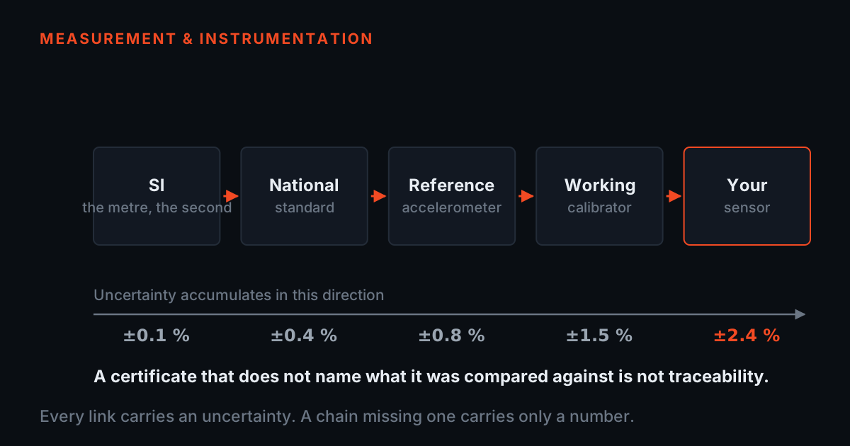
If you want the rest of the measurement-trust argument, the companion article on calibration and traceability covers what happens after the cable — how a sensitivity value is verified and what a traceable certificate actually proves. For formal, examined competence, the TCAT programme on the services page runs proctored examinations at exams.tieraonline.in.
TIERA instruments that do this work.
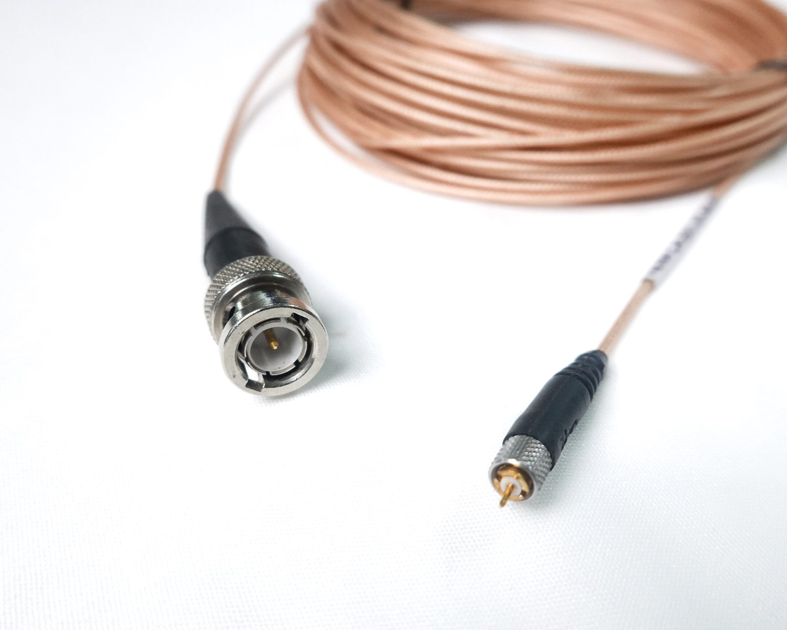
Low-Noise Coaxial Sensor Cable
The low-noise treated construction this article is about, terminated for the usual field pairing: microdot at the accelerometer, BNC at the instrument.
- Part
- CA-101-5-M-B
- Construction
- Low-noise tin-plated copper braid coaxial
- Connectors
- 10-32 / M5 microdot to BNC
- Length
- 5 m standard
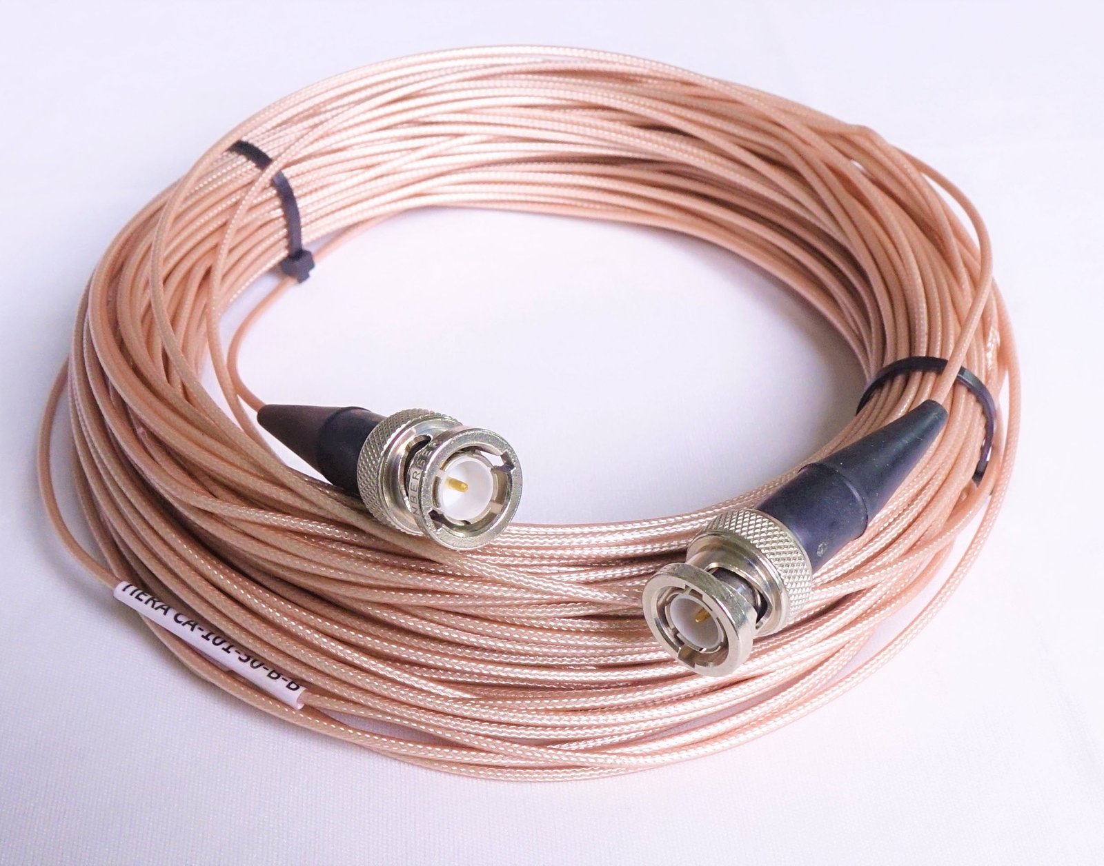
Low-Noise Coaxial BNC Cable
Same low-noise coaxial construction, BNC at both ends — the extension and bench cable for instrument-side runs.
- Part
- CA-101-5-B-B
- Construction
- Low-noise tin-plated copper braid coaxial
- Connectors
- BNC male / female, both ends
- Length
- 5 m standard
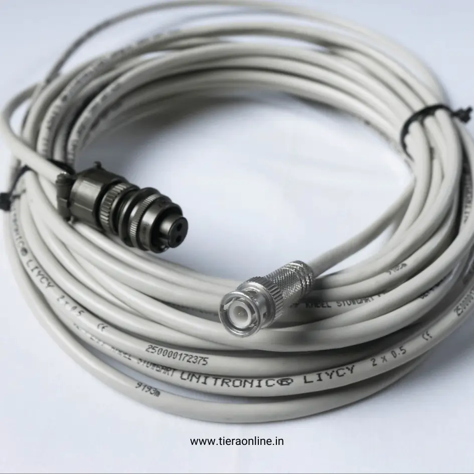
Vibration Sensor Cable – Amphenol 2 Pin MIL to BNC
The rugged industrial pairing: a two-pin circular MIL connector that keeps contact under vibration, into a BNC at the analyser.
- Part
- CA-102-5-A-B
- Construction
- Tinned copper braid, 2-core twisted shielded
- Connectors
- Amphenol 2-pin circular MIL to BNC
- Length
- 5 m standard
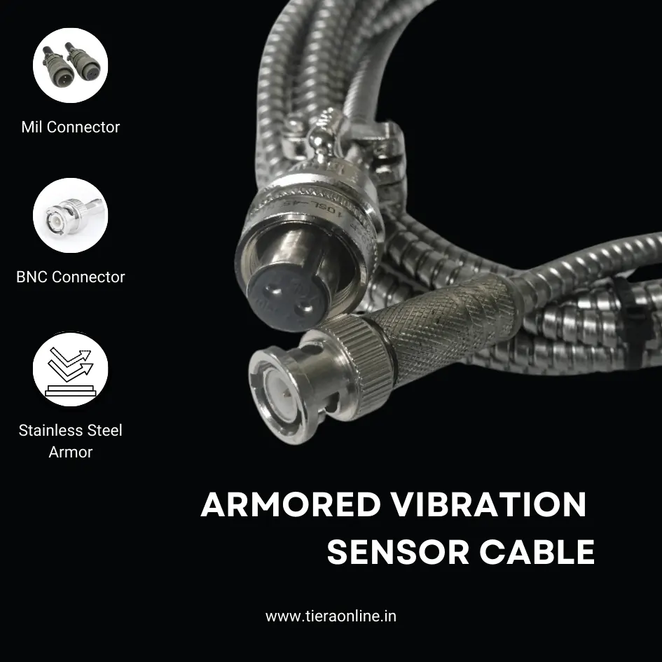
Armored Vibration Sensor Cable
For runs where abrasion, crush and dragging are the real threat — the stainless-steel outer takes the mechanical damage instead of the signal path.
- Part
- CA-103-5-A
- Construction
- Tinned copper braid, 2-core twisted shielded, stainless-steel outer armor
- Connectors
- 2-pin circular MIL to bare wires / BNC
- Length
- 5 m standard

Input/Output Cables for Dynamic Sensors (Coiled)
Walk-around routes: the coil absorbs the length change so the joint at the connector does not, and there is no slack dragging on the floor.
- Part
- CA-105-5-A-B
- Type
- Coiled accelerometer cable
- Connectors
- 2-pin MIL to BNC
- Best for
- Flexibility, space saving and repeated extension
Sensors & Accessories
The rest of the chain the cable plugs into — accelerometers, mounts and junction boxes selected to work together.
- Cables
- Low-noise coaxial (CA-101) and armored SS outer (CA-103), 5 m standard length
- Mounting
- SS304 triaxial block, magnetic mount, adhesive pad set
- Accelerometers
- TACPB-10T3 uniaxial MEMS IEPE, plus industrial, compact and low-frequency variants
- Routing
- Vibration junction boxes for multi-point tests
From the TIERA store
The kit for this job
What we would actually put in front of someone doing the measurement this post describes — not the whole catalogue.
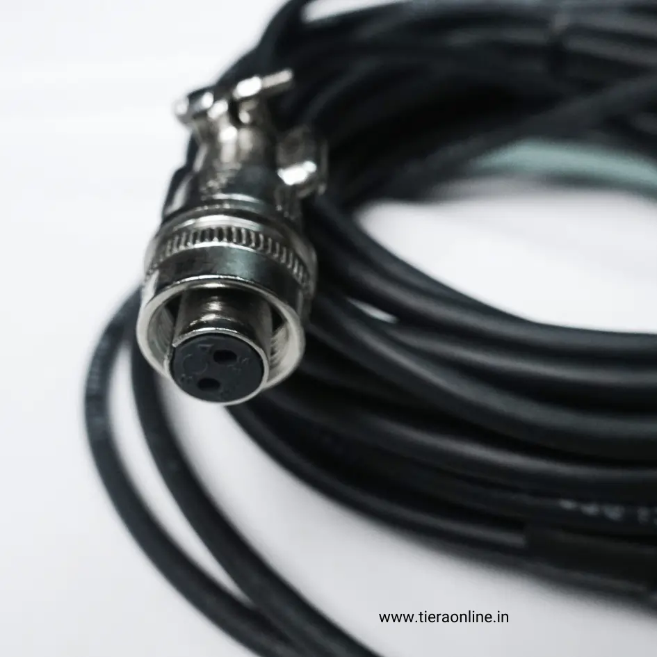 Accelerometer Sensor CableCA-102-5-D-B : Tinned Copper Braid 2 Core Twisted Shielded Cable – One side 2 Pin Circular MIL Connector other side BNC Connector₹1,500View →
- Armored Vibration sensor cableCA-103-5-A : Tinned Copper Braid 2 Core Twisted Shielded Cable with Stainless Steel Outer Armor – One side 2 pin Circular MIL Connector other side Bare wires / BNC Connector₹2,300View →
- Low-Noise Coaxial Sensor CableCA-101-5-M-B: Low-Noise Tin plated copper braid Coaxial cable – one end 10-32 / M5 Microdot Connector other end BNC Connector₹2,200View →
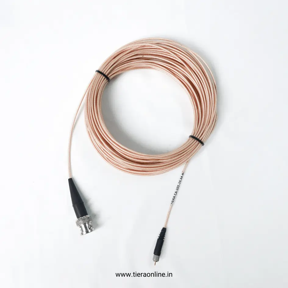 Low-Noise Cable 10-32 Microdot to BNCCA-101-5-M-B: Low-Noise Tin plated copper braid Coaxial cable – one end 10-32 Microdot Connector other end BNC Connector₹2,200View →
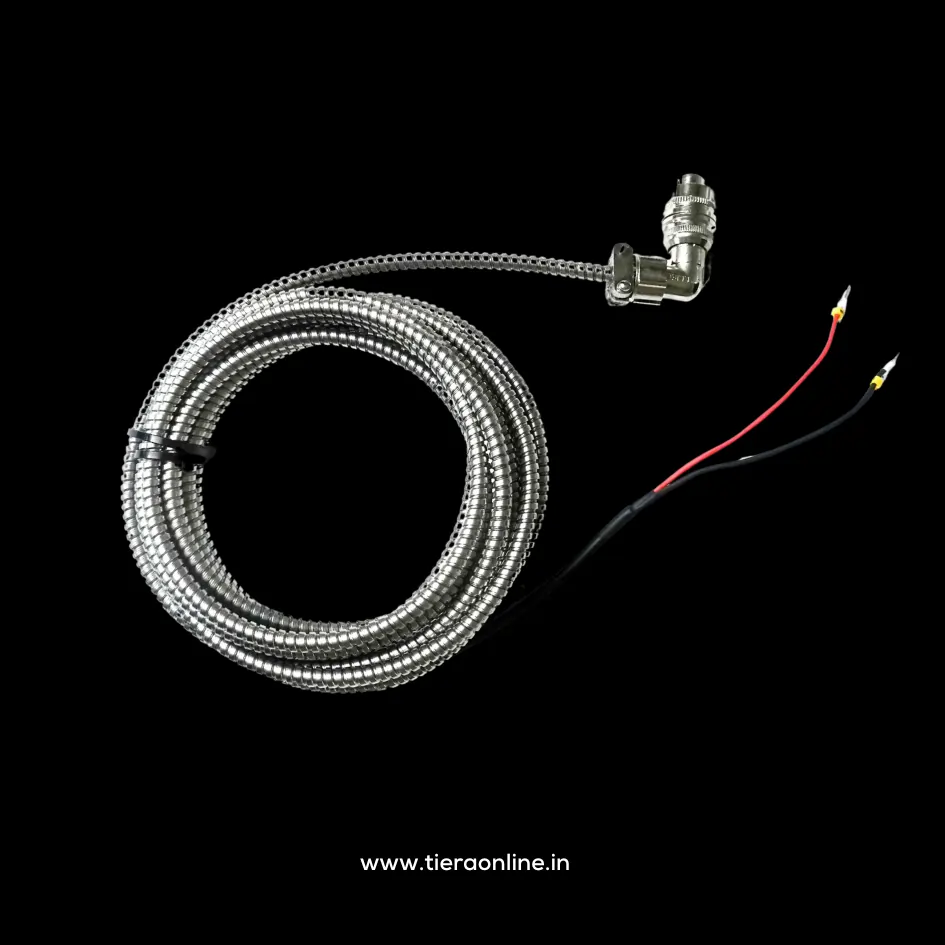 Right-angle Accelerometer cable with SS outer ArmorCA-103-5-RD : Tinned Copper Braid 2 Core Twisted Shielded Cable with Stainless Steel Outer Armor – One side 2 pin Right Angle MIL Connector other side Bare wires or BNC Connector₹2,500View →
Use cases
Where this shows up in the field
Buy the cable as a measurement component, not as a length of wire
TIERA stocks the constructions this article argues for: low-noise treated coaxial cable (CA-101) for the triboelectric problem, two-core twisted shielded cable with a rugged two-pin MIL connector (CA-102) for industrial field work, stainless-steel armored cable (CA-103) where abrasion and crush are the real risk, and coiled cables for walk-around routes. Five metres is standard across the range, with datasheets published openly in the TIERA datasheets repository.
If your measurement chain already exists and something in it is not adding up — a stubborn mains-frequency line, a noise floor that moves between visits, bearing lines that come and go — the cable and its grounding are the first two things worth checking, and we are happy to work through it with you rather than sell you a cable you do not need.
- CA-101 low-noise coaxial — microdot-to-BNC and BNC-to-BNC, 5 m standard
- CA-102 two-core twisted shielded with 2-pin circular MIL connector, into BNC
- CA-103 stainless-steel armored, straight or right-angle MIL, bare wire or BNC
- Custom junction boxes for multi-point and permanent installations, supplied with a delivery test report for THD, noise floor and frequency response
Where this sits on the TIERA learning ladder.
The theory behind this article is covered free, in full, by the TIERA 101 primers: Accelerometer & DAQ Selection 101, Measurement Setup 101. They are self-paced, interactive, and end in an exam and a certificate.
TCAT adds instructor-led depth on building a measurement chain you can defend — sensor, cable, mounting and settings — with proctored exams that certify competence; the free primers explain, TCAT verifies.
TIERA 101 is a free introductory primer, not an accredited ISO certification, and its hours do not count towards the formal training ISO 18436 requires.