


What a Signal Conditioner Actually Does — and When You Genuinely Need One
An IEPE accelerometer is not a passive sensor — it contains an amplifier that has to be fed a constant current before it will produce anything at all. Understanding that one fact explains constant-current supplies, bias voltage, cable-length limits, and most of the field faults that get blamed on a 'dead sensor'.
The sensor is not passive
A charge-mode piezoelectric accelerometer produces an electrical charge and nothing else. It needs a charge amplifier to turn that into a usable voltage, and until it gets one, the signal is so high-impedance that a few metres of ordinary cable will ruin it.
An IEPE accelerometer — the type most people now use, also sold as ICP®, CCLD, Deltatron® and IsoTron® depending on who made it — solves this by putting the amplifier inside the sensor, right at the crystal. That is a genuinely good idea: the fragile high-impedance signal never leaves the housing, and what travels down your cable is a low-impedance voltage that ordinary coax handles happily.
But that built-in amplifier needs power, and it has only two wires to work with — the same two wires carrying the signal out. So the power has to travel in along the same pair the signal travels out. That single constraint is the reason a constant-current source exists, and the reason almost everything else in this article behaves the way it does.
Constant current, and the bias voltage that tells you the truth
The conditioner pushes a constant current — typically 2 to 20 mA, with 4 mA a common default — up the signal wire. The sensor's internal amplifier draws what it needs and sits at some DC voltage, usually somewhere between 8 and 14 V. The vibration signal then rides on top of that DC level as a small AC wobble. A capacitor at the conditioner's output blocks the DC and passes the AC on to your analyser.
That resting DC level is called the bias voltage, and it is the single most useful diagnostic in the whole measurement chain — because it tells you the state of the sensor and the cable before you have looked at a single spectrum:
Bias near 0 V — a short circuit. The cable is crushed, a connector is wet, or the sensor has failed short. Bias near the supply rail (typically 24–30 V) — an open circuit. A broken conductor, a connector not seated, or a sensor failed open. Bias in the normal band but drifting — moisture ingress, or a sensor being cooked beyond its temperature rating. Bias correct and stable — the chain is electrically healthy, and any problem you then see is a real measurement problem.
A conditioner that reports bias voltage per channel turns a twenty-minute fault hunt into a five-second look. On a route where you are moving one sensor between dozens of points, that check is worth more than any feature on the front panel.
When you do not need a conditioner at all
This is the part product pages usually skip. If your DAQ already has IEPE inputs, you do not need a separate conditioner. The constant-current source is built in, switchable per channel, and that is the end of the discussion. Every PhonoVibe channel is IEPE-capable, so for a straightforward vibration measurement the answer is simply to switch it on.
A standalone conditioner earns its place in four specific situations, and it is worth being honest that these are the only four that matter:
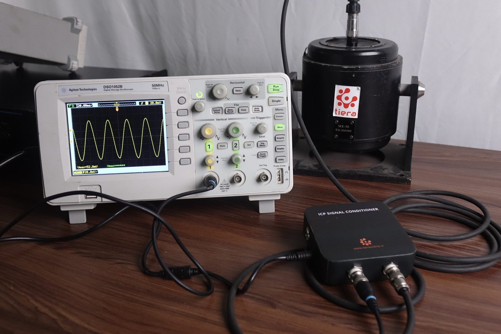
Your DAQ has no IEPE. A general-purpose voltage card, an oscilloscope, a PLC analogue input, an older acquisition system — none of them will power an IEPE sensor, and without power the sensor outputs nothing. A conditioner sits between them and makes the sensor work.
You need gain before the cable run. A low-sensitivity sensor and a long cable in an electrically noisy plant is a bad combination. Amplifying at the conditioner, close to the sensor, improves what arrives at the far end. Amplifying at the analyser after the noise has been picked up does not.
You need filtering at the front end. A conditioner with a switchable high-pass removes the DC drift and settling ramp that will otherwise eat your dynamic range; a low-pass helps keep out-of-band energy from folding back into your measurement.
You need channel isolation. On large installations, ground loops between separately-earthed machines inject mains hum into everything. An isolated conditioner breaks that loop.
Cable length, current, and the ceiling nobody mentions
There is a real physical limit on how far you can run an IEPE sensor, and it is not about signal loss — it is about the amplifier's ability to drive the cable's capacitance at high frequency.
Coaxial cable has capacitance, typically around 100 pF per metre. The sensor's internal amplifier has to charge and discharge that capacitance every cycle, and the current available to do it is whatever is left over from the constant-current supply after the amplifier has taken its own bias current. Push the frequency up, or the cable length up, and you eventually run out of current. When you do, the signal does not vanish — it distorts, and it distorts at the top of your frequency range first.
That is a nasty failure mode, because it looks like a measurement result. A bearing-envelope band at 5 kHz on the end of a 100 m cable driven at 2 mA can be quietly clipped while the 1× at 25 Hz looks perfect. Nothing in the data announces the problem.
The practical rule: more current buys more cable and more bandwidth. At 4 mA you are comfortable to a few tens of metres at full bandwidth. For long runs, raise the drive current toward 10–20 mA and check the sensor's rating first — and if you are running hundreds of metres, stop using IEPE for that channel and use a 4–20 mA loop-powered sensor designed for the distance.
How to choose, in one paragraph
Count the channels you need now and add the ones you will need within a year, because channel count is the thing people under-buy. Confirm the drive current is adequate for your longest cable at your highest frequency of interest. Insist on per-channel bias monitoring — it will pay for itself the first time a cable fails. Take switchable high-pass filtering if you measure anything that settles slowly. And if your DAQ already does IEPE and your cables are short, buy nothing: the box you need is the one already in front of you.
TIERA instruments that do this work.
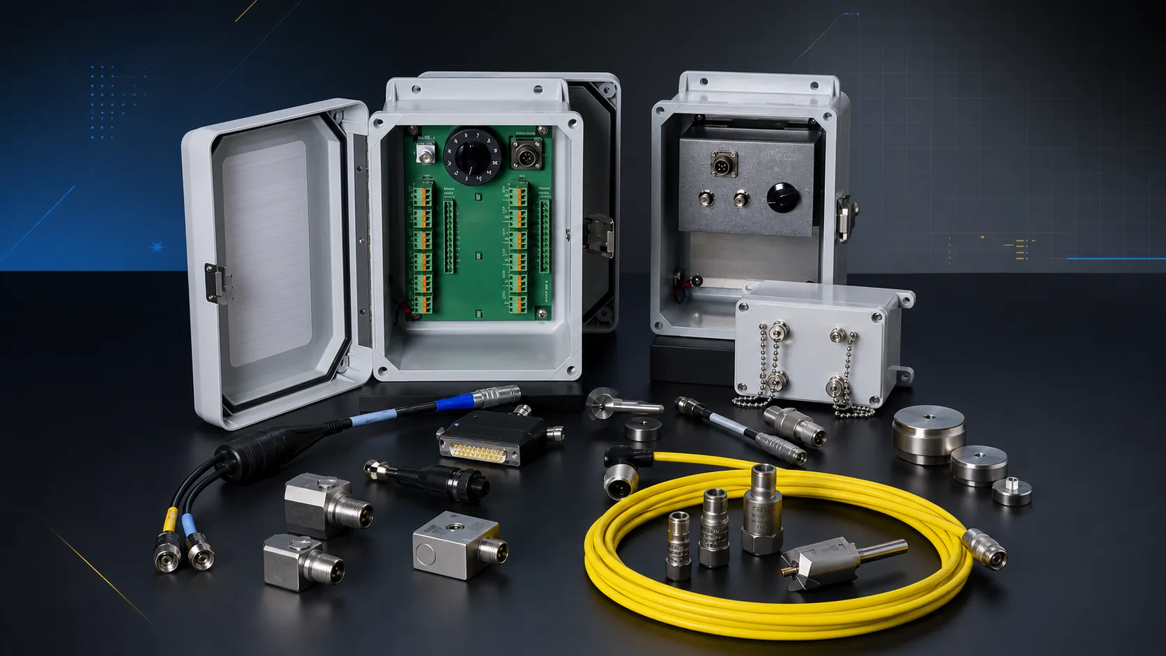
TSP Series IEPE Signal Conditioners
Constant-current drive with per-channel bias readout — so a dead cable announces itself instead of hiding in your data.
- Variants
- Single-channel and 4-channel
- Drive
- Constant-current IEPE supply
4-Channel IEPE Power Source
The straightforward answer when your existing DAQ has voltage inputs but no IEPE supply.
- Channels
- 4
PhonoVibe Series — Sound & Vibration DAQ
IEPE drive already built into every channel — if this is your DAQ, you need no separate conditioner.
- Channels
- 2, 4, 8 and 16
- Resolution
- 24-bit
From the TIERA store
The kit for this job
What we would actually put in front of someone doing the measurement this post describes — not the whole catalogue.
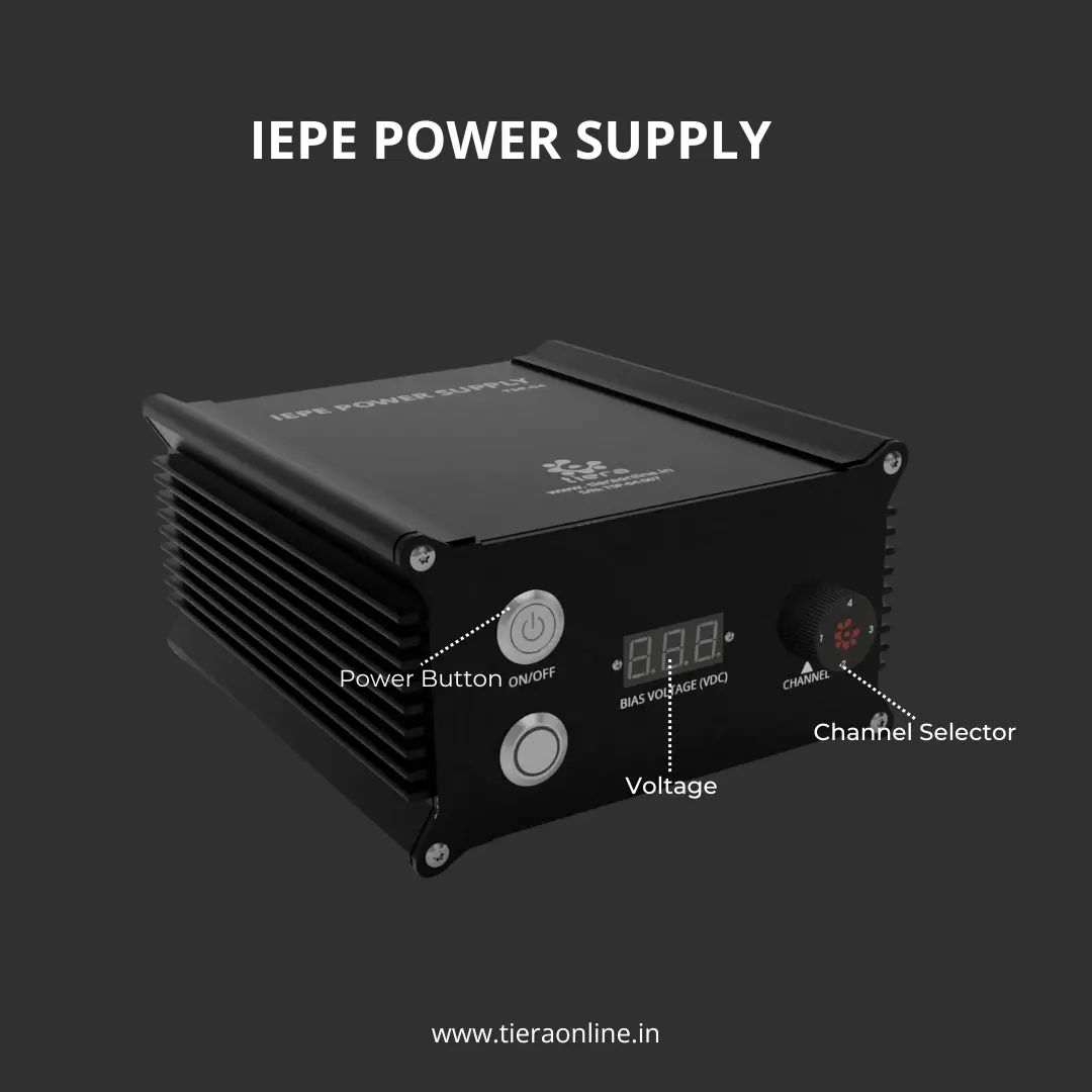 Four Channel IEPE Power Source-TSP 04Low Cost Customizable Connect ICP/IEPE Sensors to the oscilloscope or Voltage Input DAQ₹54,000View →
 TSP 02- Single Channel IEPE Power SourceLow Cost Customizable Connect ICP/IEPE Sensors to the oscilloscope or Voltage Input DAQ₹27,600View →
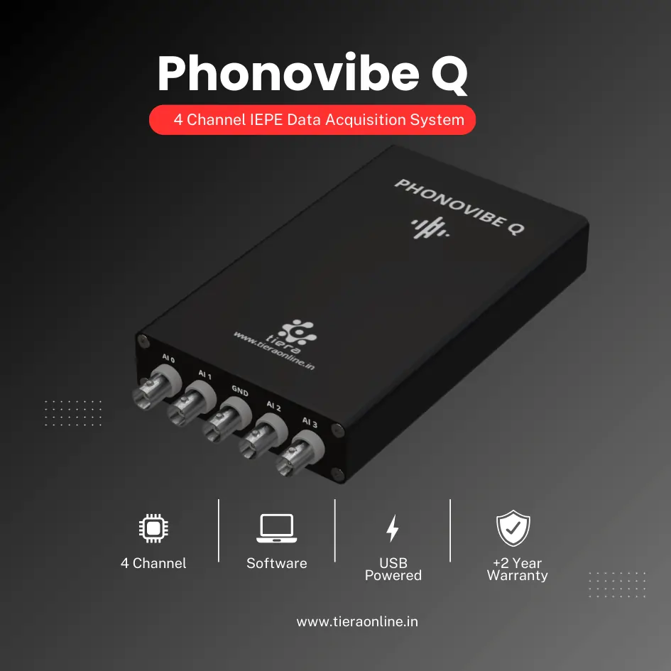 4 Channel IEPE Data Acquisition System – Phonovibe QFour Channels Standard plug & play USB Powered Take data from accelerometers, microphones, hammers, or any other IEPE Sensors T- VIB Software to acquire time waveforms, frequency spectra, overall vibration levels, FRF’s and octave measurements ** Windows 10 or above Operating System ** T-VIB Software base version comes with Time and Spectrum with Post processor TSAP 201. Check out TVIB Software regarding more module options.₹2,88,000View →
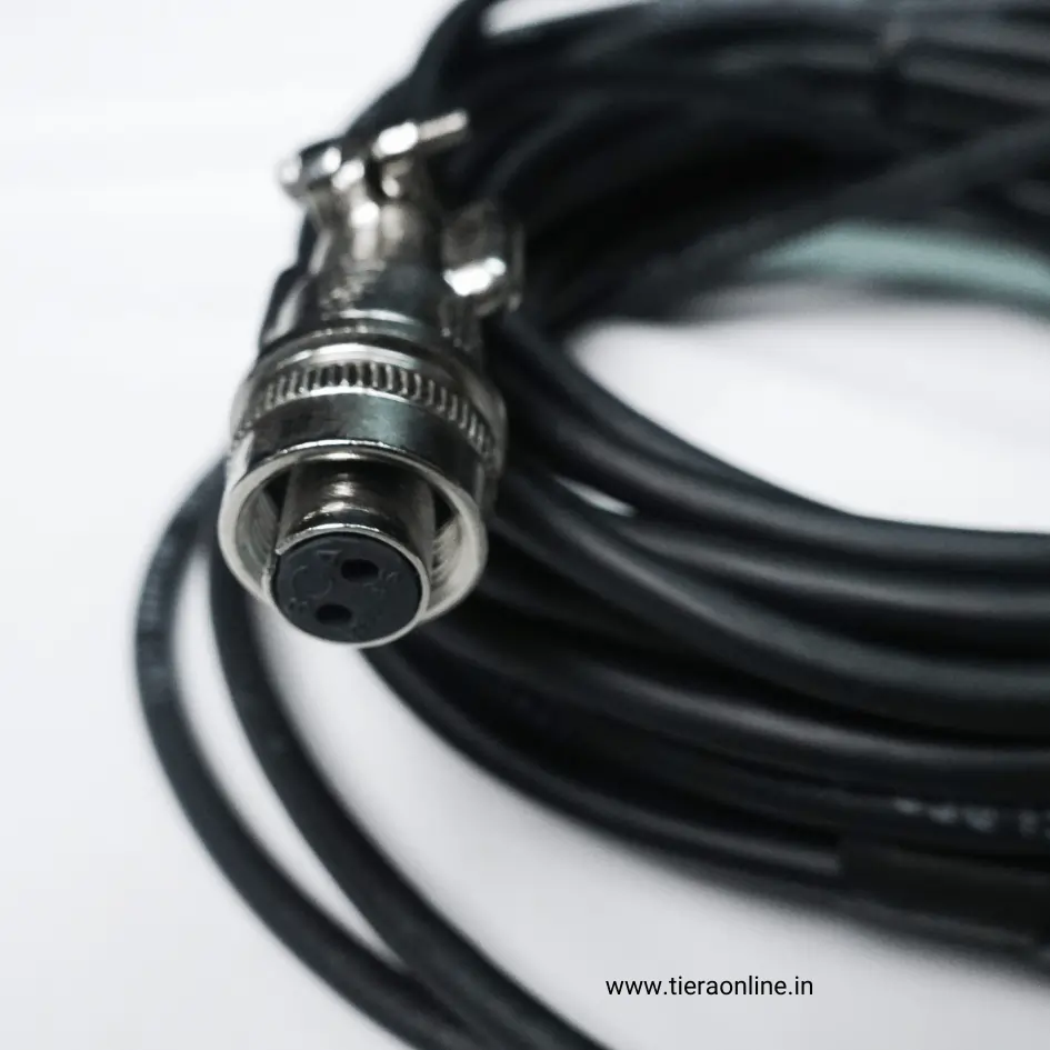 Accelerometer Sensor CableCA-102-5-D-B : Tinned Copper Braid 2 Core Twisted Shielded Cable – One side 2 Pin Circular MIL Connector other side BNC Connector₹1,500View →
Use cases
Where this shows up in the field
Power the sensor properly, or measure nothing you can trust.
Most 'faulty sensor' calls we take are a supply or a cable, not a sensor. A conditioner that shows you bias voltage per channel converts that whole class of problem into a glance.
If you already own a DAQ with IEPE inputs, we will tell you so rather than sell you a box you do not need.
- TSP series — single and 4-channel conditioning with bias monitoring
- PhonoVibe — IEPE drive on every channel, no external conditioner needed
- Cables and connectors specified for your actual run length
Where this sits on the TIERA learning ladder.
The theory behind this article is covered free, in full, by the TIERA 101 primers: Accelerometer & DAQ Selection 101, Measurement Setup 101. They are self-paced, interactive, and end in an exam and a certificate.
The primer covers the sensor and the chain that powers it. Diagnosing a chain that is subtly wrong — distortion at the top of the band, a ground loop, a bias that drifts under temperature — is Cat II territory.
TIERA 101 is a free introductory primer, not an accredited ISO certification, and its hours do not count towards the formal training ISO 18436 requires.