Automotive NVH splits into two jobs that share an instrument and share almost nothing else. Development wants to know why — which order, which mode, which mount. The line wants to know whether — pass or fail, in seconds, on every unit, without failing good parts.
Development and validation
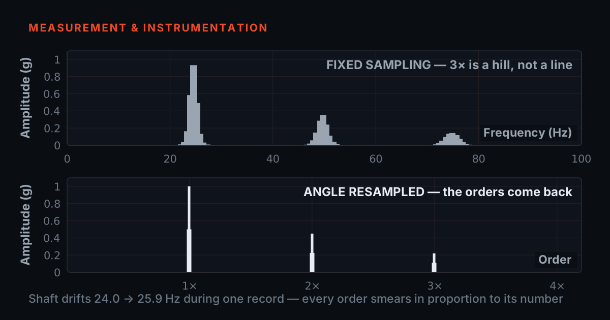
A driveline problem is usually an order problem: the frequency moves with speed, so a fixed-frequency spectrum smears it into a hill and hides it. Order analysis against a tachometer reference puts it back into one bin, and gear mesh with its sidebands becomes readable rather than suggestive.
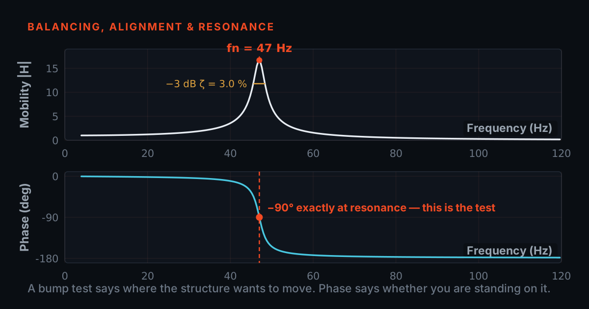
The other half of development is structure. A mount, a bracket or a panel with a natural frequency near an operating order will amplify a force that is otherwise unremarkable — and no amount of balancing fixes a resonance. Telling the two apart is a measurement, not a judgement call: is it resonance, or is it the force? shows how the answer falls out of a bump test and a run-up. Modal analysis and structural dynamics is the workflow when the structure itself is the suspect.
End-of-line testing
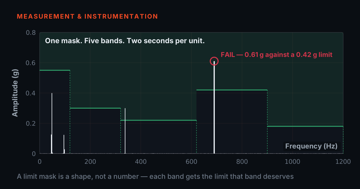
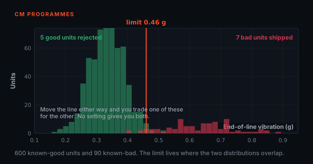
An end-of-line NVH station is a measurement wrapped in a decision. It needs a repeatable fixture, a repeatable run profile, a measurement short enough for takt time and a limit set from data. End-of-line quality testing is the workflow; setting pass/fail limits without guessing is the part most stations get wrong, because a round-number limit is a limit that was never measured.
The failure mode to design against is not a missed defect — it is a station that drifts. A fixture that loosens, a sensor whose mounting resonance moves, an operator variation in seating the part: each shifts the distribution under the limit until good parts start failing and somebody widens the limit.
The instrumentation
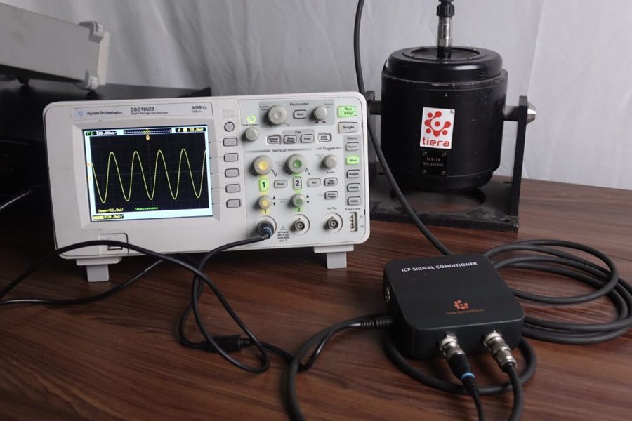
PhonoVibe supplies 2 to 16 simultaneous IEPE channels for accelerometers, microphones and force sensors, so vibration and sound are captured on one time base. TVIB does the analysis — waveform, spectrum, order analysis, FRF — and the TB 210 balancing module handles rotor correction when the answer is unbalance rather than design. Sensors, magnetic and adhesive mounts and cabling come from the same catalogue, which matters more than it sounds: the mount is part of the instrument, and a magnet with the wrong contact can delete the very band a bearing or gear defect lives in.
The standards this work is judged against
Rotating-machinery vibration severity is evaluated under the ISO 20816 series, by machine class and mounting rather than by one universal number. Rotor balance quality grades come from the ISO 21940 series (formerly ISO 1940). Analyst competence is defined by ISO 18436-2. TIERA builds to these and describes them; a production programme should work from its own controlled copies.
Where to start
For a development problem, start with order tracking on variable speed. For a line station, start with end-of-line quality testing and bring the takt time, the part, and what “bad” currently means to the conversation.
The workflows behind this
Each one is a full measurement route with its own instrument list.
End-of-Line Quality Testing
Automated spectral alarm pass/fail on every unit leaving the production line — driveshafts, pumps, motors, gearboxes — using PhonoVibe DAQ and TVIB NDT RAM.
Open the workflow →Modal Analysis and Structural Dynamics R&D
Hammer and shaker-based FRF testing, frequency-response characterisation, and mode-shape extraction for mechanical R&D teams and structural dynamics labs.
Open the workflow →