When the Speed Will Not Sit Still: Smeared Spectra and Order Tracking
On a VFD-driven machine a perfectly good analyser can produce a useless spectrum: shaft speed drifts during the average, every shaft-related peak walks across bins, and the 10th order smears ten times as badly as the 1st. Order tracking — resampling the signal against shaft angle using a tacho pulse — collapses the smear back into sharp lines. A hard-concepts walk through why, with a live rig: dial in speed wobble, pile on averages, and watch the Hz spectrum die while the order spectrum holds.
The spectrum that moved while you measured it
- Smear is proportional to order number: a 1% speed change moves the 1st order by 1% of one shaft frequency and the 10th by ten times as many hertz.
- So the high-order region — gear mesh, blade pass — degrades first and worst, while low orders survive mild drift untouched.
- This is not leakage. A window cannot fix it, because the window cannot stop the shaft.
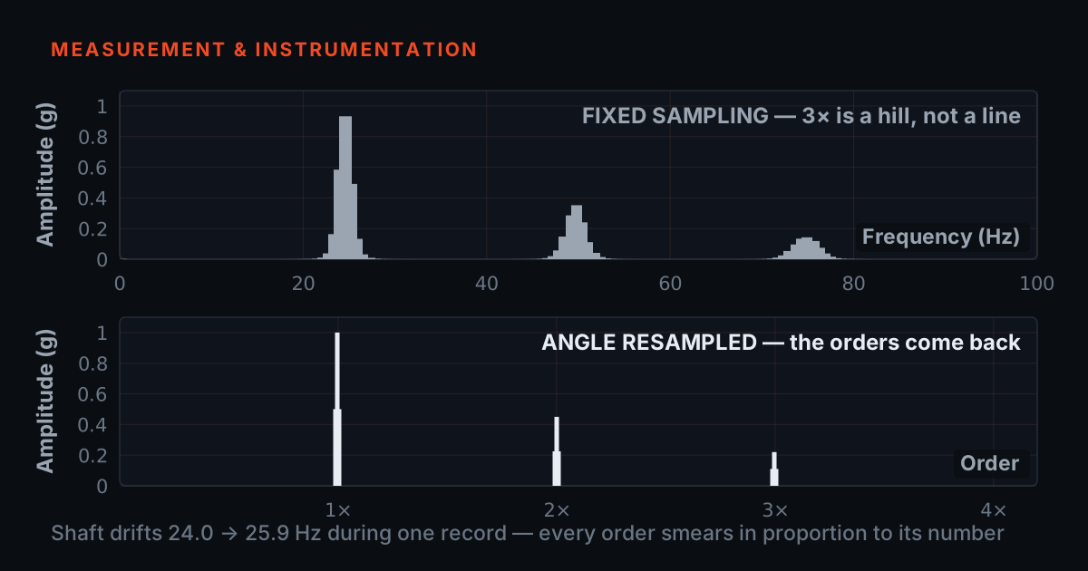
The FFT makes a quiet promise on your behalf: that the frequency content of the record is stationary — whatever tones are present hold their frequency from the first sample to the last. A fixed-speed machine roughly keeps that promise. A machine on a variable-frequency drive does not. Load swings, the drive hunts, the process demands a ramp — and the shaft that was at 1,200 RPM when the record started is at 1,215 RPM when it ends. Every component locked to that shaft — 1×, harmonics, gear mesh, blade pass — changed frequency mid-record.
A peak that moves during the record does not land in one bin; it walks across several and its energy is divided among them. The result is a shorter, wider bump — a smear. And the damage is proportional to order number: a 1% speed change moves the 1st order by 1% of one shaft frequency, but it moves the 10th order by 1% of ten shaft frequencies — ten times as many hertz, ten times as many bins. Low orders survive mild drift; the high-order region, where gear mesh and blade-pass live, degrades first and worst.
This is not leakage, though it looks superficially similar. Leakage is the record's edges lying about a perfectly steady tone — a windowing problem, covered in our window comparator — and a Hann window largely fixes it. Smearing is the tone itself refusing to hold still, and no window can fix that, because the window cannot stop the shaft.
Why averaging — usually your friend — makes it worse
- Averaging assumes each record is a fresh look at the same spectrum. On a drifting machine each record is a look at a different spectrum.
- Both instincts betray you: longer records give the speed more time to move, and more averages paint the peak across every place it visited.
- The trap is that the spectrum looks cleaner as it becomes less true — a beautifully low floor with a featureless hump where the mesh family used to be.
The reflex on a noisy measurement is more averages, and against random noise the reflex is right: averaging smooths the floor and steadies the estimate. But averaging assumes each record is a fresh look at the same spectrum. On a drifting machine each record is a look at a slightly different spectrum — the 10th order sat near 199 Hz in this record, 202 Hz in the next, 197 Hz in the one after. Averaging those magnitudes does not sharpen the peak; it paints the peak's energy across the union of all the places it visited.
So the two knobs you would normally reach for both betray you. Longer records make it worse: finer bins mean the same drift in hertz spans more of them, and a longer capture gives the speed more time to move. More averages make it worse: each extra record widens the smear a little more while flattering the noise floor around it. The end state on a VFD drive is a spectrum with a beautifully low floor and a broad, featureless hump where the gear-mesh family used to be — the peaks you needed for diagnosis, and the sidebands whose spacing names the faulty shaft (drive them in the gear-mesh sideband explorer), dissolved into it.
That combination is the trap: the spectrum looks cleaner as it becomes less true. An analyst who has never seen smearing reads the hump as 'broadband energy — maybe looseness, maybe noise' when the machine is actually producing sharp, well-behaved tones at frequencies the analyser simply refused to hold still long enough to see.
Order tracking: analyse the revolution, not the second
- A 43-tooth gear meshes exactly 43 times per turn at any speed. Shaft-locked content is unsteady in time and perfectly regular per revolution.
- Order-spectrum resolution is set by revolutions captured, not seconds: 8 revolutions gives 1/8-order bins whether they took half a second or five.
- The speed variation has not been filtered out or estimated away. It has been made irrelevant by a change of variable.
The escape is to stop asking 'how many times per second?' and ask 'how many times per revolution?'. A gear-mesh tone is unsteady in time only because the shaft is unsteady in time — per revolution it is perfectly regular: a 43-tooth gear meshes exactly 43 times per turn at any speed. So instead of sampling the signal at equal steps of time, resample it at equal steps of shaft angle. In that angle domain, every shaft-locked component becomes stationary again, and the FFT's promise is kept.
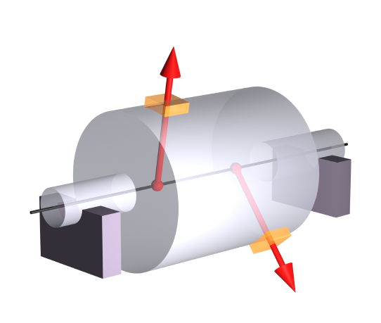
Doing this needs a measured angle axis, and that is what the tacho (or keyphasor) provides: a pulse at a known shaft position, typically once per revolution from an optical sensor on a strip of reflective tape or a proximity probe over a keyway. Between pulses the processor interpolates shaft phase, then interpolates the vibration record at the instants where phase crosses each angle step — say 32 evenly spaced points per revolution, every revolution, fast or slow. This is synchronous resampling: computed after capture from an ordinary uniformly sampled record plus the pulse train, no exotic hardware in the signal path.
The FFT of the angle-domain record is an order spectrum. Its axis is not hertz but orders — multiples of shaft speed — and its resolution is set by revolutions captured, not seconds: 8 revolutions gives 1/8th-order bins whether those revolutions took half a second or five. Unbalance sits at order 1, a 43-tooth mesh at order 43, at every speed. The speed variation has not been filtered out or estimated away; it has been made irrelevant by a change of variable.
Two domains, two casualties — and both are useful
Synchronous resampling is not a free sharpening filter — it is a trade. The angle domain is only 'still' for components locked to the reference shaft. Anything that does not follow that shaft — the 50 Hz mains-related tones of a nearby motor, a structural resonance, something running on the next machine — is steady in hertz and therefore unsteady in orders. Exactly the components that smeared in the Hz spectrum are sharp in the order spectrum, and vice versa.
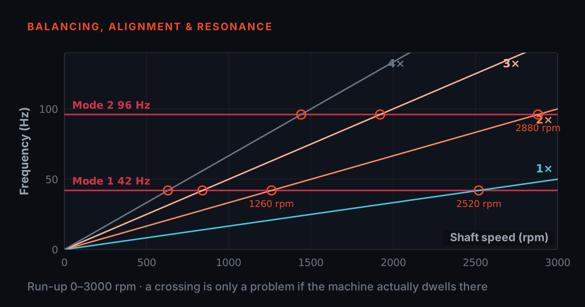
Read as a pair, the two spectra become a classifier. A component that is sharp in orders and smeared in hertz is shaft-driven: unbalance, misalignment, gear mesh and its sidebands. A component that is sharp in hertz and smeared in orders is fixed-frequency: electrical, structural, something on another machine. Rolling-element bearing tones sit in neither box cleanly, and it is worth being precise about why, because it is routinely got wrong: BPFO, BPFI, BSF and FTF are proportional to shaft speed — they track the drive just as faithfully as 1× does — but they land on non-integer orders, and cage slip means the proportionality constant itself drifts by a percent or two. A resonance is the clearest case — as the shaft sweeps, orders climb through a fixed resonance, which is precisely the crossing you watch on a Campbell diagram during a run-up (drive one yourself in the Campbell resonance explorer). Order tracking is the measurement that makes run-up and coast-down data readable at all.
That has a practical consequence worth stating carefully, because the short version — 'order tracking does not work on bearings' — is wrong. It does work: resampling removes almost all of a bearing tone's smear, because almost all of that smear came from the shaft moving. What it leaves behind is a small residual from the slip, and the fact that the tone sits between integer orders, so a harmonic cursor set on integers will not line up with it and an order-domain average across widely different speeds still blurs it a little. Call them non-integer-order rather than non-synchronous. On a variable-speed machine the practical route is still envelope analysis over short, speed-segmented records, with order tracking underneath it if you have the tacho — the two are complementary, not alternatives.
Drive it: smear a spectrum, then rescue it
The rig below is honest maths, not an illustration. Each record is a genuinely non-stationary signal: shaft orders 1, 5 and 10 (amplitudes 1.0, 0.6 and 0.5 g) ride a shaft whose speed really ramps within every half-second record — a fresh random drift per record, bounded by your slider — plus a fixed 50 Hz mains tone and a little noise. The left panel Hann-windows and FFTs the raw record. The right panel first simulates a 1-pulse-per-revolution tacho, interpolates phase between pulses, resamples the same record at 32 equal angle steps per revolution over 8 revolutions, and FFTs that. Both views magnitude-average over your chosen number of records.
Start at ±1% drift and 4 averages: in the Hz view the 10× peak already reads about 0.44 g against a true 0.500 g, while 1× has not moved at all and 5× has lost about 3% — the order-proportional rule from the first section, live. Hold the averages at 4 and sweep the drift instead: 1× barely moves — 1.00 g at rest, 0.99 g at ±3% — while 5× falls from 0.600 to about 0.45 g and 10× collapses from 0.502 to about 0.28 g. Now sweep the averages at fixed drift and watch what averaging does not do: the Hz reading does not converge on anything. At ±2% it wanders between roughly 0.31 and 0.43 g as you add records, never settling and never approaching the truth, because each record was a different spectrum. The order-view readout sits between 0.48 and 0.49 g at every drift and every average count on the slider. Then do the reverse experiment: wind drift to zero and note the two views agree — order tracking buys nothing on a machine that holds speed.
What you need in practice — and when you can skip it
- The whole hardware requirement is a tacho pulse recorded on a channel that shares the accelerometer's clock — small, and absolute.
- Size the sample rate so the highest order of interest stays below Fmax at the top of the speed range, not at nominal.
- On a machine that genuinely holds speed, order tracking buys nothing but complexity — spend the money on sensor placement and resolution instead.
The hardware requirement is small but absolute: a speed reference captured alongside the vibration. That means a tacho pulse — reflective tape and an optical sensor, or a proximity probe over a keyway — recorded on a channel that shares the same clock as the accelerometer channels, so pulse times and vibration samples line up exactly. Once-per-rev is the workable minimum; more pulses per revolution pin down the phase better between pulses, which matters exactly where smearing hurt you most — high orders, where any interpolation error is multiplied by the order number. The vibration channels also need enough sample-rate headroom that the highest order of interest stays below Fmax at the top of the speed range, not just at nominal (front-end rules in sample rate, Fmax and anti-aliasing).
What about just shortening the record so the speed cannot move far within it? It is a real but partial workaround. A shorter record does shrink the drift per record — and costs you resolution in exact proportion, since bin width is 1/T. You can trade until the smear at your highest order of interest is smaller than a bin, but on a drive that wanders a few percent you usually run out of resolution before you run out of smear, and averaging across records still smears whatever remains because each short record sits at a different speed. Order tracking removes the conflict instead of splitting the difference.
And when speed genuinely holds — a fixed-speed machine on a stiff supply, drift well under half a bin at your highest order across the whole average — order tracking buys you nothing but complexity. A plain Hz spectrum with a Hann window is the right measurement, and the money is better spent on sensor placement and resolution. One honest caveat closes the loop: everything above assumed a measured speed reference. Tacholess order tracking — estimating instantaneous speed from the vibration signal itself, usually by chasing a strong harmonic through a time–frequency map — exists, but it is a harder and less reliable problem: pick the wrong ridge or lose it in noise, and the 'corrected' spectrum smears or, worse, sharpens the wrong family. If you can fit tape and a sensor, fit them.
A representative case — and where to learn this properly
A representative case, not a specific customer: a gearbox on a VFD-driven process line shows rising overall vibration, but every spectrum from the site analyser is the same story — clean low orders, then a broad hump between roughly 8× and 12× where the mesh frequency should be. More averages were tried; the hump got smoother and the conclusion got no closer. Logging drive speed alongside showed ±2% wander within each capture — at the 10th order, a walk of some twenty bins. With a strip of reflective tape, an optical tacho into a spare simultaneous channel, and order-domain processing, the hump resolved into a sharp mesh order carrying 1×-spaced sidebands on the input shaft — a developing gear fault that the smeared spectrum had been hiding in plain sight, found without any change of sensor.
The theory this post leans on — FFT stationarity, resolution, windowing, and the sampling chain — is covered in TIERA's free primers at 101.tieraonline.in: Signal Processing 101 for the transform-side assumptions and Measurement Setup 101 for tacho placement and channel choices. The primers are free introductory courses for onboarding and refreshing fundamentals, not accredited ISO certification. When you need formally assessed competence, the TCAT programme (details at /services) adds structured coursework and proctored examinations at exams.tieraonline.in. The fastest way to make order tracking stick, though, is to break a spectrum yourself: put a rig on a VFD, sweep the speed, watch the smear appear — then add the tacho and watch it collapse.
TIERA instruments that do this work.

TMFSS — Machinery Fault Signature Simulator
Reproduces this exact experiment on a bench: sweep the speed with the VFD, take the speed reference from the built-in tachometer's analogue output, and watch a spectrum smear and recover under controlled, repeatable conditions.
- Speed control
- VFD with WiFi software
- Tachometer
- Built-in, analog output
- Faults (Macro)
- 30+ base kit, extensible with add-on kits
- Foundation
- Solid rigid base
- Warranty
- 1 year; AMC available

PhonoVibe Series — Sound & Vibration DAQ
Order tracking needs vibration and the speed reference on one clock: PhonoVibe samples every input simultaneously, so a spare voltage channel can log the tacho signal in lockstep with the accelerometers.
- ADC resolution
- 24-bit
- Sampling
- Simultaneous on every input
- Channels
- 2 / 4 / 8 / 16 (BNC), ±10 V or ±5 V input
- Sensor power
- 24 V, 4 mA constant current (IEPE/ICP/CCLD)
- Connectivity
- USB, plug-and-play (Windows 10/11)
TVIB — Sound & Vibration Analysis Software
The modular analysis layer for this job: the TSAP201 base module handles the windowed, averaged spectra, and order tracking is on TVIB's add-on module list for rotating-equipment diagnostics on machines that will not hold speed.
- Base module
- TSAP201 — free with PhonoVibe
- FFT size
- Up to 102,400 points
- Averaging
- Exponential, linear, peak hold, selectable windowing
- Licence
- Perpetual; 14-day fully-unlocked trial
From the TIERA store
The kit for this job
What we would actually put in front of someone doing the measurement this post describes — not the whole catalogue.
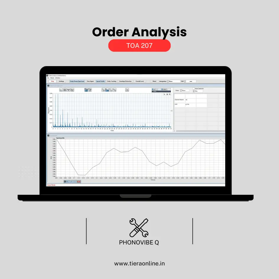 TOA 207 – Order Analysis(Phonovibe Q)Use Cases Machine Condition Monitoring Run up Coast Down Test₹57,600View →
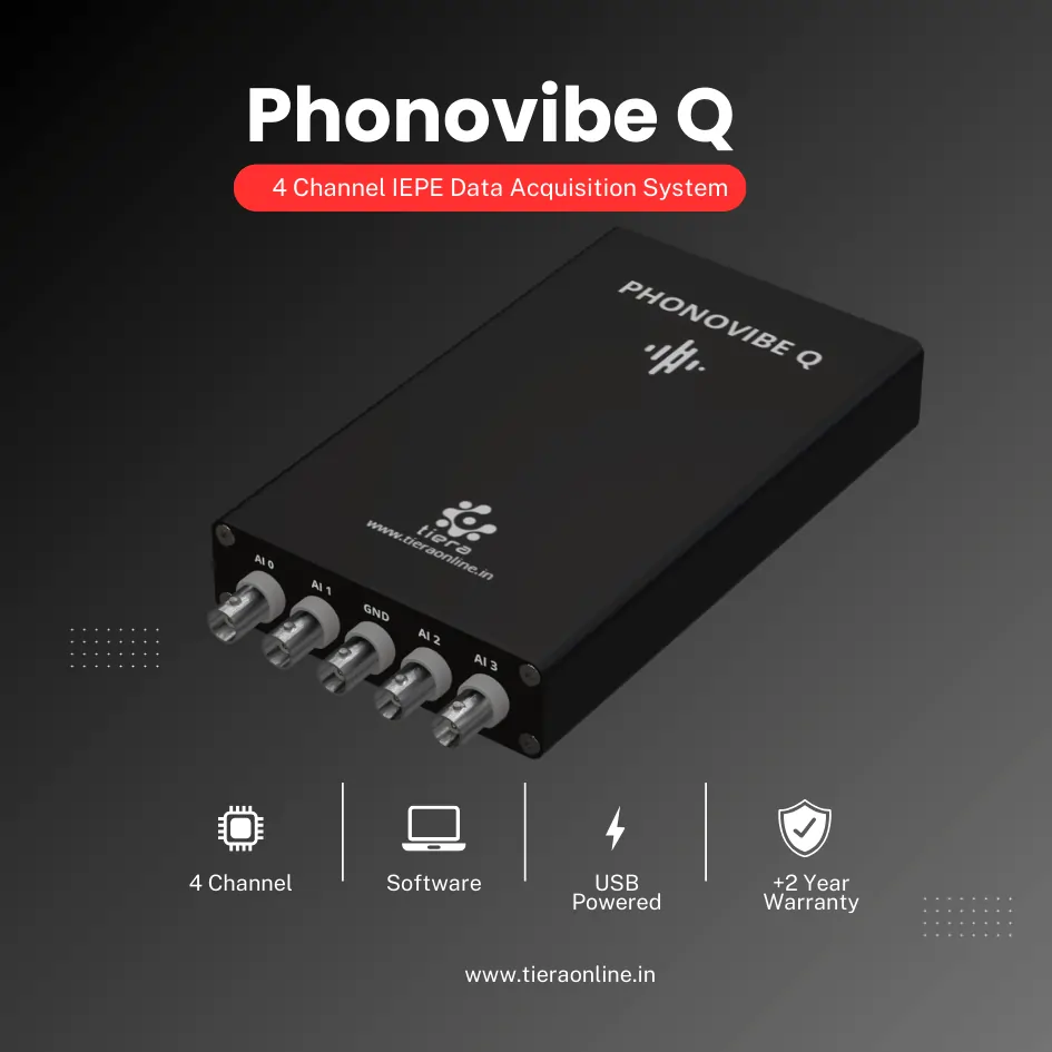 4 Channel IEPE Data Acquisition System – Phonovibe QFour Channels Standard plug & play USB Powered Take data from accelerometers, microphones, hammers, or any other IEPE Sensors T- VIB Software to acquire time waveforms, frequency spectra, overall vibration levels, FRF’s and octave measurements ** Windows 10 or above Operating System ** T-VIB Software base version comes with Time and Spectrum with Post processor TSAP 201. Check out TVIB Software regarding more module options.₹2,88,000View →
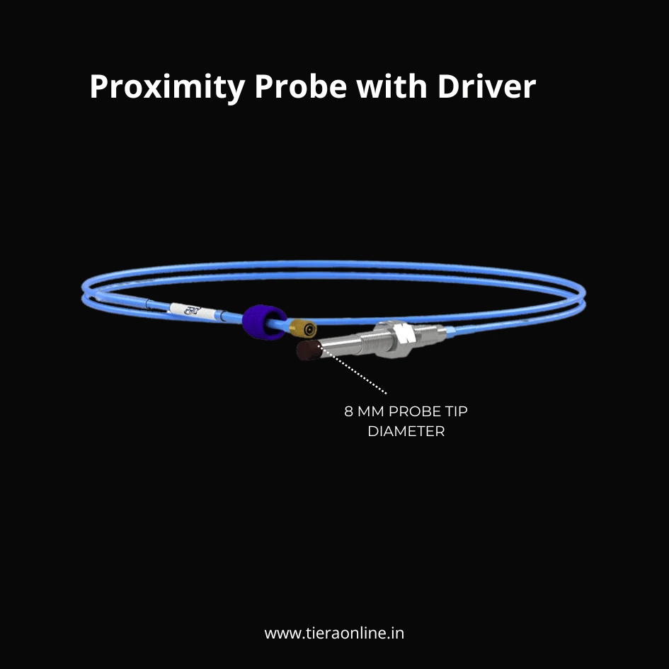 Proximity Probe with DriverPROXIMITY PROBE, 8 MM PROBE TIP DIAMETER, WITH 3/8-24 OR M10X1 CASE THREAD Measure shaft vibration and displacement on machinery with fluid film bearings. Durable PPS over-molded probe tips withstand harsh conditions when monitoring critical machinery such as turbines and compressors. Complete hardware system is compatible with all standard condition monitoring software EDDY CURRENT DRIVER COMPATIBLE WITH 8 MM PROXIMITY PROBE SYSTEMS, VOLTAGE OUTPUT API Standard 670 specified format Isolated voltage output standard at BNC and terminal block Vout and Com Upgraded to include SecureLock connector₹88,000View →
Use cases
Where this shows up in the field
A rig that wobbles on demand, a DAQ that keeps time, software that straightens it out
Everything in this post reduces to three needs: a controlled way to produce speed variation, a capture chain that records vibration and a speed reference on one clock, and analysis that can work in the order domain. The TMFSS simulator covers the first two ends of the experiment by itself — VFD speed control to make the smear appear on demand, and a built-in tachometer with an analogue output to serve as the speed reference — which is why it is the rig we put in front of analysts learning exactly this failure mode.
For capture, PhonoVibe DAQs sample every channel simultaneously at 24 bits with IEPE sensor power, so accelerometers and the tacho signal land on a common timebase — the non-negotiable prerequisite for synchronous resampling. On the analysis side, TVIB is modular: TSAP201 (bundled free with every PhonoVibe) covers windowed, averaged narrowband spectra, and order tracking sits on TVIB's add-on module list for rotating-equipment diagnostics. Tell us your speed range and highest order of interest and we will spec the chain end to end.
- TMFSS — VFD speed control plus built-in tachometer (analogue output): reproduce smearing and its fix repeatably on a bench
- PhonoVibe DAQ — 24-bit, simultaneous sampling on 2 to 16 channels, so vibration and speed reference share one clock
- TVIB — TSAP201 base analysis bundled free; order tracking among the add-on modules for variable-speed diagnostics
- 14-day fully-unlocked TVIB trial to run the workflow on your own recordings first
Where this sits on the TIERA learning ladder.
The theory behind this article is covered free, in full, by the TIERA 101 primers: Signal Processing 101, Measurement Setup 101. They are self-paced, interactive, and end in an exam and a certificate.
The free primers at 101.tieraonline.in cover the FFT's stationarity assumption, resolution and the tacho-equipped measurement chain; the formal TCAT programme (see /services) adds structured coursework and proctored examinations at exams.tieraonline.in for analysts who need assessed, certificated competence on rotating machinery.
TIERA 101 is a free introductory primer, not an accredited ISO certification, and its hours do not count towards the formal training ISO 18436 requires.