Phase: The Ruler Most People Never Pick Up
Amplitude says how much, frequency says how often — phase says how the machine is actually moving. A mini explainer plus a live simulator: pick a fault, toggle the measurement direction, and read the phase pattern that separates faults the spectrum cannot.
Amplitude says how much. Phase says how.
- Unbalance, a bent shaft, misalignment and eccentricity all put their energy at 1×. Amplitude and frequency can tell you something is wrong there; only phase tells you which one.
- Phase is the timing of the vibration against a fixed mark on the shaft — it turns a list of peak heights into a picture of how the machine is actually moving.
Every vibration reading answers three questions. Amplitude: how much is it shaking? Frequency: how often? Those two get all the attention, because they arrive free with every spectrum. The third — phase — answers the question the other two cannot: how is the machine actually moving? Are the two ends of the train swinging together or in opposition? Is the coupling being bent or the rotor being flung? Phase is the timing of the vibration against a fixed mark on the shaft, and it turns a list of peak heights into a picture of motion.
It matters because several common faults are near-identical in the spectrum. Unbalance, a bent shaft, misalignment and eccentricity all put their energy at 1× running speed, with varying amounts of 2×. An analyst staring only at amplitudes can tell that something is wrong at 1× — and then guess. Phase is the ruler that measures which one it is, and most people never pick it up.
How a phase number is made
- Absolute phase at one point means little. The diagnostic content is in differences between points, taken in the same direction.
- So the reference cannot move mid-survey: one tape, one tacho position, one sensor orientation, for every reading you intend to compare.
- Conventions differ between instruments — some display lead rather than lag, and integrating to velocity or displacement shifts the number. This post quotes lag, 0–360°, throughout.
You need a reference. A tachometer or laser pointed at a strip of reflective tape — or a keyphasor probe watching a keyway on larger machines — fires once per revolution and defines 0°. The analyser then measures how far behind that pulse the 1× vibration peak arrives at each bearing. Our convention, in this post and in the simulator below: phase is that lag, quoted 0–360°, with every sensor mounted in the same orientation. Be aware that conventions differ between instruments and textbooks — some display lead rather than lag, and integrating acceleration to velocity or displacement shifts the number — so state yours before comparing readings with anyone.
Two practical rules follow. First, the reference cannot move mid-survey: one tape, one tacho position, for every reading you intend to compare. Second, absolute phase at a single point means little — the diagnostic content is in differences between points, taken in the same direction. A sensor mounted upside-down reads 180° away from its right-way-up twin, which has sent more than one analyst chasing a coupling problem that was actually a mounting problem. There is also a two-channel shortcut: measure two points simultaneously on a DAQ that samples its channels together, and the cross-channel phase difference comes out directly, no tacho required — though you lose the fixed 0° anchor.
Drive the train: pick a fault, read the phase
Below is a motor–coupling–pump train with two bearings per machine: B1 and B2 on the motor, B3 and B4 on the pump, shown side-on and end-on. Pick a fault and the train animates in that fault's characteristic motion, exaggerated so you can see it, while the phase readings at each bearing update for the direction you have selected — horizontal, vertical or axial. The verdict line underneath states what the pattern proves, and just as importantly, when the direction you are looking in proves nothing.
The values are typical teaching values, not measurements — on a real machine expect scatter of ±30° or so, and expect structures and resonances to shade the numbers. What survives the scatter is the pattern: readings that agree, readings that flip by roughly 180°, and readings that refuse to repeat.
Reading the tell-tales
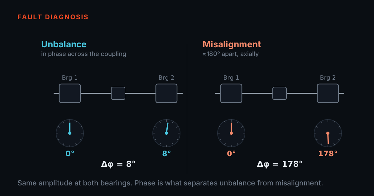
- Unbalance: all bearings roughly in phase radially, H and V about 90° apart at each bearing, axial quiet. Parallel misalignment: a roughly 180° radial flip across the coupling, usually with strong 2×.
- Angular misalignment and a bent shaft both show the 180° flip in the axial direction — which is why a bent shaft impersonates unbalance well enough to fool a spectrum.
- Looseness has no tidy map at all: the phase jumps between surveys. The refusal to repeat is itself the finding.
The patterns you just drove are the working vocabulary of phase analysis. Unbalance: all bearings roughly in phase radially along the train, horizontal and vertical about 90° apart at each bearing, axial quiet — the train swings as one because a rotating heavy spot drags everything the same way at the same instant. Parallel misalignment: a roughly 180° flip in the radial phase across the coupling, usually with strong 2×, because the offset shafts lever each machine in opposition. Angular misalignment: the same flip, but in the axial direction, where the bent coupling alternately pushes the machines apart and pulls them together.
Bent shaft: roughly 180° between the two ends of the bent shaft in the axial direction — the ends nod in opposition about the bow — while radially it impersonates unbalance well enough to fool a spectrum. Looseness: no tidy map at all; the phase jumps between surveys, often by 90° or 180°, because a joint is rattling through its clearance rather than following the structure. Notice what made each call: not a number, but a comparison — and in a specific direction. That is why the simulator makes you toggle H, V and A: the direction that reveals a fault is part of its signature.
A representative case
A representative case, not a specific customer: a 2,950 RPM end-suction pump reads high at 1× on both pump bearings, with a modest 2×. The spectrum is compatible with unbalance — and the impeller had recently been off for a wear-ring change, so unbalance is everyone's favourite theory. Balancing gear is booked. Someone measures phase first: horizontal, motor bearings around 60–65°, pump bearings around 240–245°. That is not the unbalance map; in-phase ends would agree within a few tens of degrees. A 180° radial flip across the coupling with 2× present says the shafts are offset — parallel misalignment.
Laser alignment finds the offset, the machine is realigned, and the 1× drops without a single trial weight. The point is not that phase was clever; it is that thirty minutes of phase reading was about to be traded for a day of balancing a rotor that was never unbalanced. The spectrum posed the question. Phase answered it.
Honest limits, and where to learn the rest
Phase patterns are indicative, not absolute. Real machines scatter their readings; operating near a resonance can swing phase by tens of degrees on its own; foundations, overhung rotors and combined faults blur the textbook maps; and a convention mix-up — lead versus lag, a flipped sensor, displacement versus acceleration — manufactures a 180° 'finding' out of nothing. A competent diagnosis combines the phase map with the spectrum, the direction the energy lives in, and the machine's history, and treats a pattern as a hypothesis to confirm — by alignment check, by trend, by inspection — not a verdict to act on blind.
If you want the foundations under this post, the free primers at 101.tieraonline.in cover them at beginner pace — Vibration 101 for amplitude, frequency and phase from first principles, and Machinery Fault Diagnosis 101 for the fault patterns driven here. TIERA 101 is a free primer, not an accredited ISO certification. For formal, examined analyst training there is the TCAT programme on our services page, with proctored examinations at exams.tieraonline.in.
TIERA instruments that do this work.

PhonoVibe Series — Sound & Vibration DAQ
Simultaneous sampling on every input keeps channels in step — multiplexed inputs smear inter-channel phase, which is precisely the quantity this post measures — so the two-channel cross-phase shortcut works as described.
- Sampling
- Simultaneous on every input
- ADC resolution
- 24-bit
- Sensor power
- 24 V, 4 mA (IEPE/ICP/CCLD)
- TEDS
- Supported
- Connectivity
- USB, plug-and-play

TVIB — Sound & Vibration Analysis Software
Puts phase to work: the TB 210 balancing module accepts a phase reference from a tachometer or laser and guides single- and two-plane correction — the once-per-rev anchor this post's convention is built on.
- Base module
- TSAP201 — free with PhonoVibe
- Balancing (TB 210)
- Single- and two-plane, with phase correction
- FFT size
- Up to 102,400 points
- Trial
- 14-day fully-unlocked evaluation licence

TMFSS — Machinery Fault Signature Simulator
Its built-in tachometer with analog output provides the once-per-rev 0° reference, so you can measure the unbalance, misalignment and looseness phase maps from this post on seeded, repeatable faults.
- Tachometer
- Built-in, analog output
- Speed control
- VFD with WiFi software
- Faults (Macro)
- 30+ base kit, extensible with add-on kits
- Foundation
- Solid rigid base
From the TIERA store
The kit for this job
What we would actually put in front of someone doing the measurement this post describes — not the whole catalogue.
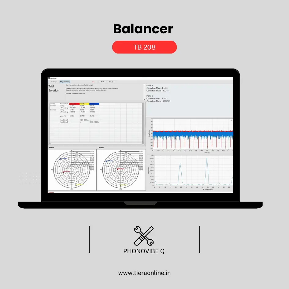 TB 208 – Balancer (Phonovibe Q)Use Cases Balancing Rotating Machineries₹69,120View →
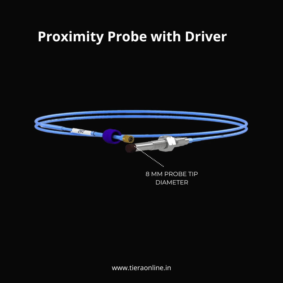 Proximity Probe with DriverPROXIMITY PROBE, 8 MM PROBE TIP DIAMETER, WITH 3/8-24 OR M10X1 CASE THREAD Measure shaft vibration and displacement on machinery with fluid film bearings. Durable PPS over-molded probe tips withstand harsh conditions when monitoring critical machinery such as turbines and compressors. Complete hardware system is compatible with all standard condition monitoring software EDDY CURRENT DRIVER COMPATIBLE WITH 8 MM PROXIMITY PROBE SYSTEMS, VOLTAGE OUTPUT API Standard 670 specified format Isolated voltage output standard at BNC and terminal block Vout and Com Upgraded to include SecureLock connector₹88,000View →
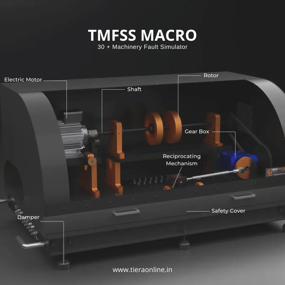 Machinery Fault Signature SimulatorTiera’s Machine Fault Simulator (TMFSS) is a valuable tool for industries and researchers, simulating over 30 real-world faults such as: Bearing faults: outer race defects, inner race defects, cage defects. Motor faults: stator faults, rotor faults, electrical unbalance. Gearbox faults: gear wear, misalignment, gear tooth damage. And more.₹13,53,600View →
Use cases
Where this shows up in the field
Phase needs two things: a once-per-rev reference, and channels that stay in step
Every reading in this post assumes hardware that preserves timing. That means a tacho or keyphasor input to anchor 0°, and a DAQ that samples all channels simultaneously — multiplexed inputs smear inter-channel phase, which is precisely the quantity you are trying to measure. Every PhonoVibe DAQ samples its inputs simultaneously at 24-bit with IEPE sensor power, so cross-channel phase survives the acquisition intact. The once-per-rev reference itself comes from the analysis side: TVIB's TB 210 module accepts a phase reference from a tachometer or a laser.
On the software side, TVIB's TSAP201 base module carries the time-and-spectrum work with harmonic cursors and multi-channel views, and the TB 210 module applies phase directly in guided single-plane and two-plane balancing. And if you want the patterns in this post under your fingers rather than in your notes, the TMFSS simulator reproduces unbalance, misalignment and looseness (bent shaft via an add-on kit) on a benchtop with a built-in tacho with analog output — measure the phase maps yourself, then break them on purpose.
- PhonoVibe D / Q / O / HD — 24-bit USB DAQs with simultaneous sampling on every input, IEPE/ICP/CCLD power and TEDS
- TVIB TSAP201 + TB 210 — spectrum and cursors, plus phase-corrected single- and two-plane field balancing; 14-day fully-unlocked trial available
- TMFSS Macro / Mini / Micro — repeatable unbalance, misalignment and looseness with a built-in tacho (analog out); bent-shaft add-on kit
Where this sits on the TIERA learning ladder.
The theory behind this article is covered free, in full, by the TIERA 101 primers: Machinery Fault Diagnosis 101, Vibration 101 (Foundations). They are self-paced, interactive, and end in an exam and a certificate.
TCAT adds structured, examined analyst training with proctored exams — the free primers cover the concepts; TCAT verifies you can apply them on a real machine.
TIERA 101 is a free introductory primer, not an accredited ISO certification, and its hours do not count towards the formal training ISO 18436 requires.