Balancing a Rotor in Place: Trial Weights, Phase and the Influence-Coefficient Method
A visual walk through field balancing — reference run, trial run, correction, verification — why every run must be at the same speed, and what an ISO 21940 balance grade really commits you to.
First, confirm it is actually unbalance
- The balanceable signature is narrow: one dominant 1× peak, radial higher than axial, and a phase that holds steady while the machine runs steady.
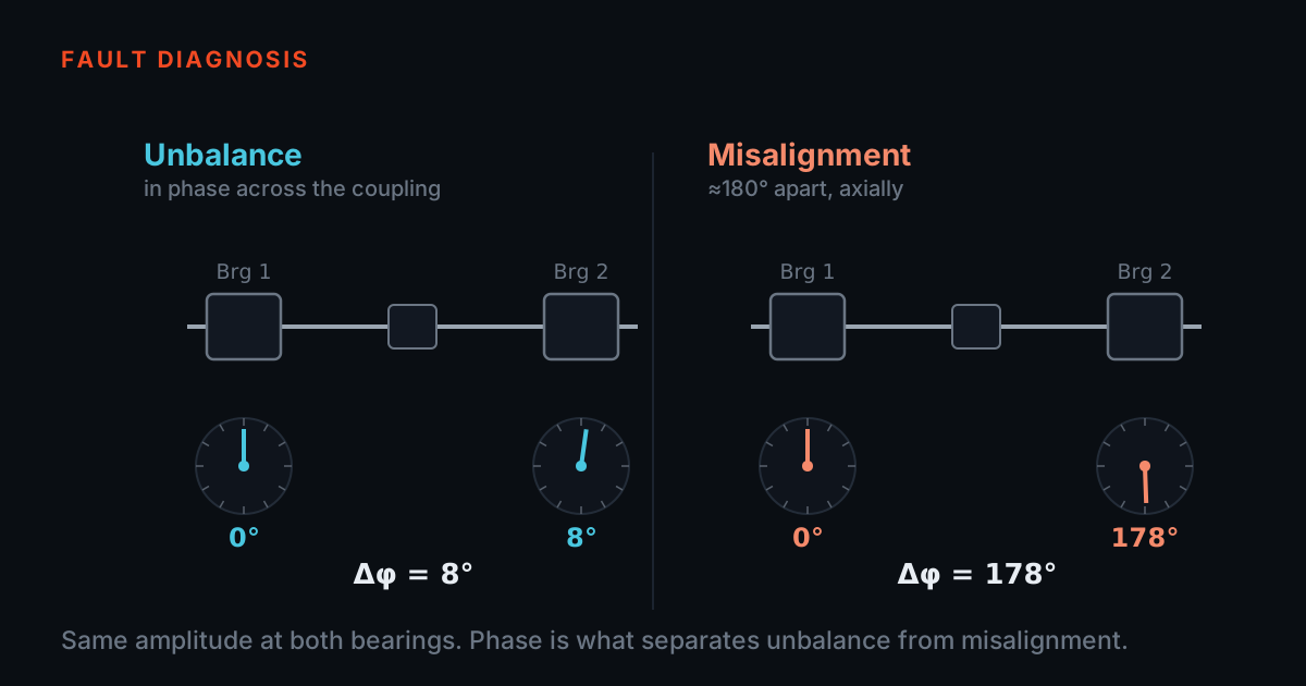
- Strong 2×, high axial 1× or wandering phase means misalignment, a bent shaft, looseness or resonance — weights fix none of them and cost you a shift.
Unbalance is the most common cause of excessive vibration in rotating machinery — which is exactly why it gets blamed for problems it did not cause. The signature is specific: a single dominant peak at 1× running speed, radial vibration higher than axial, and a phase reading that holds steady while the machine runs steady.
If the spectrum shows strong 2× energy, high axial 1×, or wandering phase, you are likely looking at misalignment, a bent shaft, looseness, or resonance. Adding balance weights to those machines wastes a shift and fixes nothing — diagnose first, balance second.
Vibration is a vector — and every run is at the same speed
- Fix the angular convention before the machine turns: phase readings and weight positions must be counted from the same reference mark and in the same angular sense.
- Every run — reference, trial, correction, verification — happens at the same speed. The influence coefficient is only valid at the speed where it was measured.
- The accelerometer and the phase reference may not move for the rest of the job.
An overall reading says how much the machine shakes; it cannot say where to put a weight. For that you need the 1× vibration as a vector — amplitude plus phase — measured against a once-per-revolution mark on the shaft. In practice: an accelerometer on the bearing housing and a tachometer or optical laser trigger on a strip of reflective tape. Neither may move for the rest of the job.
One more thing has to be fixed before the first run, and it is the one that sends weights to the wrong side of a rotor: the angular convention. The 1× phase readings and the weight positions must be counted from the same reference mark and in the same angular sense. Most analysers report 1× phase as a lag, so the usual field practice is to lay the weight angles out against the direction of rotation to match. The influence-coefficient arithmetic is indifferent to which sense you choose — it is not indifferent to using one sense for the phase and the other for the weights. Write the convention on the job sheet before the machine turns.
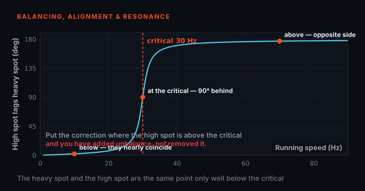
One rule is non-negotiable: every run — reference, trial, correction, verification — happens at the same speed. The rotor-bearing system's response to unbalance changes with speed, drastically near a resonance, so the influence coefficient you are about to measure is only valid at the speed where you measured it. Change speed between runs and the arithmetic still gives an answer; it will just be wrong.
The trial weight teaches the rotor to answer
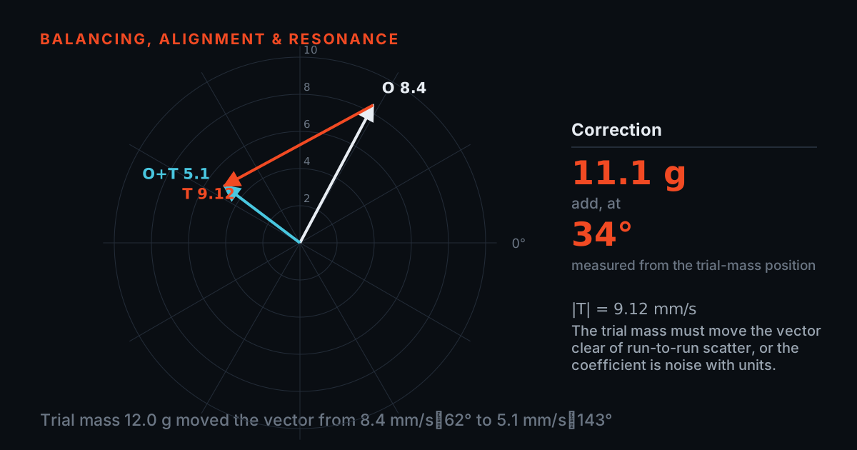
You cannot locate the heavy spot from one measurement, because you do not yet know how this rotor, in these bearings, on this foundation, responds to unbalance. So you ask it: bolt a known trial mass at a known angle, run again, and subtract the two vectors. What remains is the trial weight's own effect — the influence coefficient — and the correction is then pure geometry: scale and rotate that effect until it cancels the original vector. TB 210 walks this sequence step by step and states the correction weight and angle directly; the diagram below is what it is doing underneath.
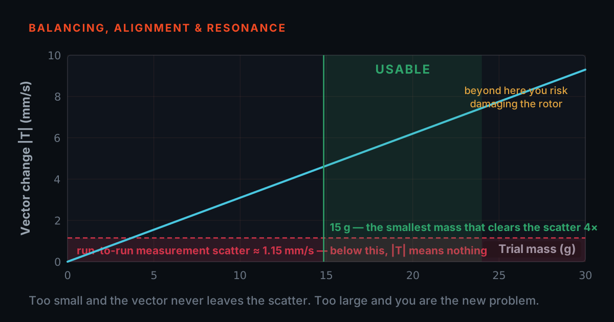
Two practical rules. Size the trial weight to matter — roughly a 30 per cent amplitude change or 30-degree phase shift, or the result is noise. And fasten it so it cannot fly off: centrifugal force grows with speed squared, and a 20-gram weight at 200 mm radius on a 3,000 RPM rotor pulls outward with roughly 400 newtons — about 40 kg of force on a part you attached by hand. Bolt it, clamp it, or weld it; never tape it. Stay out of the rotor's plane during run-up.
Correction: trial weight off, or on — never halfway
Before fitting the correction, decide explicitly: does the trial weight come off, or stay on? Both are legitimate — the software simply computes a different correction for each case, and TB 210 prompts for exactly this. What is never legitimate is the halfway state: removing the weight but applying the leave-it-on correction, or forgetting which state the rotor is in. That re-injects a known unbalance, and the verification run will find it. Tag the rotor; write it down.
If the correction angle lands where there is no hole or vane, split the mass across the two nearest positions so the vector sum is unchanged. And on long rotors — where a weight at one end shifts the vibration at both bearings — the same discipline runs twice: two trial planes, four influence coefficients, solved together. TB 210 handles single-plane and two-plane jobs in one workflow.
What an ISO 21940 grade actually commits you to
- A grade like G 6.3 limits residual specific unbalance — permissible unbalance per kilogram of rotor mass, multiplied by service speed, expressed in mm/s.
- It commits the rotor, not the bearing reading, which is why a shop-balanced rotor can still shake on a resonant structure.
- Report both: residual unbalance against the grade, and before-and-after 1× at each bearing.
Acceptance should be stated against a standard — ISO 21940-11, the successor to the ISO 1940 balance quality grades that TB 210 checks residuals against. A grade like G 6.3 is a limit on residual specific unbalance: permissible unbalance per kilogram of rotor mass, multiplied by service speed, expressed in mm/s.
Note what it does not promise: a G grade commits the rotor, not the bearing reading. The vibration you measure at the housing also depends on the machine's stiffness and foundation, which is why a shop-balanced rotor can still shake on a resonant structure — and why field balancing, which minimises vibration on the machine as installed, is often the more useful commitment. Report both: residual unbalance against the grade, and before-and-after 1× at each bearing.
A representative job, not a specific customer
The numbers below are typical values for this class of work, not a record of any customer or machine. A 1,480 RPM fan with an overhung impeller reads 9.8 mm/s at 1×, phase 118 degrees, after a blade repair — a clean, balanceable fault. A 30-gram trial weight bolted at the 0-degree mark moves the reading to 7.1 mm/s at 74 degrees; the solver returns 43 grams at 314 degrees with the trial weight removed, split across the two nearest holes.
Verification at the same speed: 1.4 mm/s. One trim pass, reusing the already-measured coefficient with no new trial run, lands below 1 mm/s, and the residual is checked against the agreed G grade. Total machine time including run-ups: under two hours. The hard part was never the arithmetic — it was changing one thing per run and holding everything else constant.
The kit, and where to learn it
The procedure above is what the TVIB TB 210 balancing module implements: tachometer or laser phase reference, a guided trial-weight sequence, automatic correction weight and angle for single-plane and two-plane jobs, and a balancing report for the maintenance file. It runs on any PhonoVibe DAQ — the two-channel PhonoVibe D makes a natural field kit, 24-bit with IEPE sensor power, USB-powered from the laptop — and on compatible third-party hardware (NI 9234/4431, Modal Shop 485B39, Sinus Apollo, DT9837). Accelerometers, cables and mountings are in our sensors and accessories range, and the TMFSS simulator generates controlled, repeatable unbalance on a benchtop so an analyst can practise the whole loop — and deliberately get the trial weight wrong — with nothing at stake.
If the vectors moved faster than you would like, the free primers at 101.tieraonline.in cover the groundwork; the Balancing & Alignment 101 course walks through phase and the method at beginner pace. TIERA 101 is a free primer, not an accredited certification. For formal, examined training there is the TCAT programme on our services page, with proctored examinations at exams.tieraonline.in.
TIERA instruments that do this work.
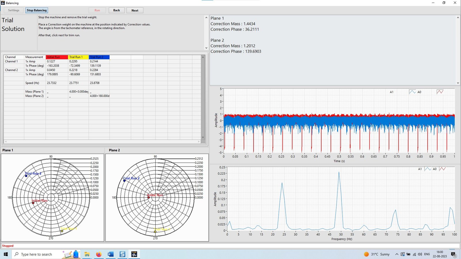
TVIB TB 210 — Two-Plane Field Balancing Module
Implements this exact procedure: guided trial-weight runs, influence-coefficient solution, and the correction weight and angle stated directly — single-plane and two-plane in one workflow.
- Balancing planes
- Single-plane and two-plane
- Phase reference
- Tachometer or optical laser trigger
- Output
- Correction weight, angle, balancing report
- Host software
- TVIB TSAP 201 base module required
- Licence
- Perpetual; 2 years free updates

PhonoVibe Series — Sound & Vibration DAQ
The field kit under TB 210: the two-channel PhonoVibe D runs vibration plus phase reference, USB-powered from the laptop, with IEPE sensor power built in.
- ADC resolution
- 24-bit
- PhonoVibe D (2-ch)
- 48 kHz · 2 Hz – 20 kHz · ±10 V
- Sensor power
- 24 V, 4 mA (IEPE/ICP/CCLD)
- Connectivity
- USB, plug-and-play

TMFSS — Machinery Fault Signature Simulator
Rehearse the whole loop — reference run, trial weight, correction — on controlled, repeatable unbalance with a built-in tachometer for phase, before the first live rotor.
- Speed control
- VFD with WiFi software
- Tachometer
- Built-in, analog output
- Faults (Macro)
- 30+ base kit, extensible
- Warranty
- 1 year; AMC available
From the TIERA store
The kit for this job
What we would actually put in front of someone doing the measurement this post describes — not the whole catalogue.
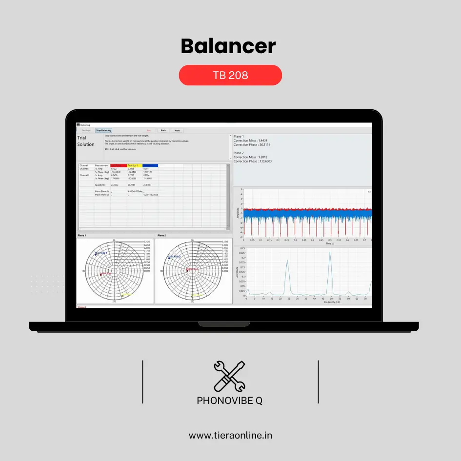 TB 208 – Balancer (Phonovibe Q)Use Cases Balancing Rotating Machineries₹69,120View →
- Balancing Kit — Phonovibe QField balancing, hardware and software together — Phonovibe Q DAQ, the TB 208 balancer application, an accelerometer and cable.Request priceView →
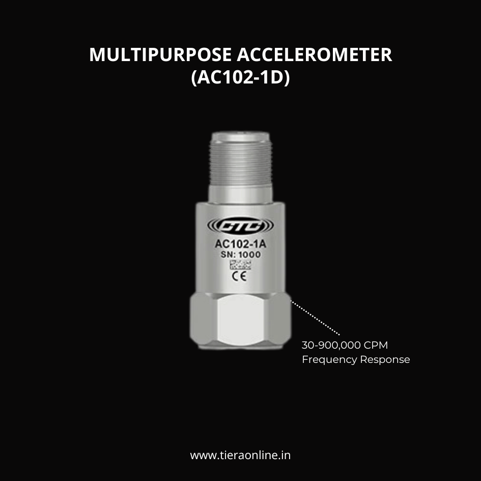 AC102-1D, MULTIPURPOSE ACCELEROMETERMULTIPURPOSE ACCELEROMETER, TOP EXIT 2 PIN CONNECTOR, 100 MV/G, ±10% 30-900,000 CPM Frequency Response (±3dB) -58 to 250 °F (-50 to 121 °C) Temperature Range Welded, Hermetic Sealing CTC’s Best Selling, Multi-Purpose Sensor Ideally Suited for Thousands of Applications₹14,750View →
Use cases
Where this shows up in the field
Ready to balance your next rotor where it stands?
The procedure in this post is exactly what the TVIB TB 210 balancing module runs. It takes its phase reference from a tachometer or optical laser trigger, walks you through the reference and trial runs with on-screen prompts, solves the influence coefficients, and states the correction weight and angle directly — for single-plane and two-plane jobs in one workflow. It then checks the residual against ISO 1940 grade limits and outputs a balancing report for the maintenance file, so the acceptance argument in the section above is written down, not remembered.
TB 210 runs on any PhonoVibe DAQ — the two-channel PhonoVibe D, 24-bit with IEPE sensor power and USB-powered from the laptop, makes a compact field kit — and on supported third-party hardware (NI 9234/4431, Modal Shop 485B39, Sinus Apollo, DT9837), so it may already fit instruments you own. If you would rather rehearse before the first live job, the TMFSS benchtop simulator generates controlled, repeatable unbalance, so an analyst can run the whole loop — and deliberately get the trial weight wrong — with nothing at stake.
- Guided single-plane and two-plane workflow with step-by-step trial-weight prompts — no polar-chart reading
- Automatic correction weight and angle, residual checked against ISO 1940 grade limits, balancing report output
- Perpetual module licence with two years of free updates; a 14-day fully-unlocked TVIB trial is available
- TMFSS simulator with VFD speed control and built-in tachometer for repeatable unbalance practice runs
Where this sits on the TIERA learning ladder.
The theory behind this article is covered free, in full, by the TIERA 101 primers: Balancing & Alignment 101. They are self-paced, interactive, and end in an exam and a certificate.
TCAT adds structured, examined analyst training with proctored exams — the free primer covers the concepts; TCAT verifies you can apply them.
TIERA 101 is a free introductory primer, not an accredited ISO certification, and its hours do not count towards the formal training ISO 18436 requires.