One Chipped Tooth, Once per Revolution: Reading Gear Mesh and Its Sidebands
The mesh tone is a gearbox's normal singing voice — its height alone proves little. A chipped tooth modulates that tone once per revolution, growing sidebands around the GMF, and their spacing names the guilty shaft. Includes a live spectrum explorer you can drive.
The gearbox's normal singing voice
- A tall mesh peak is not by itself a fault. Its height moves with load, alignment, tooth finish, temperature and the path from mesh to sensor — it can double between two readings on a gearbox that is perfectly healthy.
- The diagnosis lives in the family of smaller peaks either side of the GMF, never in the GMF's own height.
A healthy gearbox is not silent — it sings. Every time a pinion tooth rolls into contact with a gear tooth, the stiffness of the mesh changes slightly, and that tiny periodic push repeats once per tooth, teeth-times per shaft revolution. The result is the gear-mesh frequency, GMF: tooth count multiplied by shaft speed. A 23-tooth pinion on a shaft turning 1,475 rpm — 24.6 revolutions per second — engages 23 × 24.6 ≈ 565 teeth every second, so this gearbox hums at 565 Hz on the day it is commissioned and on every healthy day after.
That is the first thing to unlearn: a tall mesh peak is not, by itself, a fault. Its height moves with load, alignment, tooth finish, temperature, and the vibration path between mesh and sensor — it can double between two measurements on a gearbox that is perfectly fine. The diagnosis does not live in the height of the singing voice. It lives in the family of smaller peaks that appears on either side of it: the sidebands.
One tone, two shafts
The two gears are locked together at the mesh, so teeth stream through the contact point at a single shared rate. Count it from either side and you must get the same number: pinion teeth × input shaft speed = gear teeth × output shaft speed. That equality is also the speed ratio — the output shaft turns at the input speed multiplied by pinion teeth over gear teeth. Our 23-tooth pinion at 1,475 rpm driving a 91-tooth gear gives an output of 1,475 × 23⁄91 ≈ 373 rpm, or 6.21 Hz; and sure enough 91 × 6.21 ≈ 565 Hz, the same GMF the pinion side gave us.
This is why the mesh peak alone can never tell you which gear is damaged: both shafts own that peak jointly. When something goes wrong on one tooth of one gear, you need a second piece of evidence to name the shaft it rides on — and the spectrum provides one, in the form of how the peaks around the GMF are spaced.
One chipped tooth, once per revolution
- The defect does not change the note the gearbox sings; it squeezes that note once per revolution of the shaft the bad tooth rides on. In signal terms the mesh tone is amplitude- and phase-modulated.
- Modulation in time is sidebands in frequency, at GMF ± 1, 2, 3… times the faulty shaft's rotational speed. The spacing, not the size, is the fingerprint.
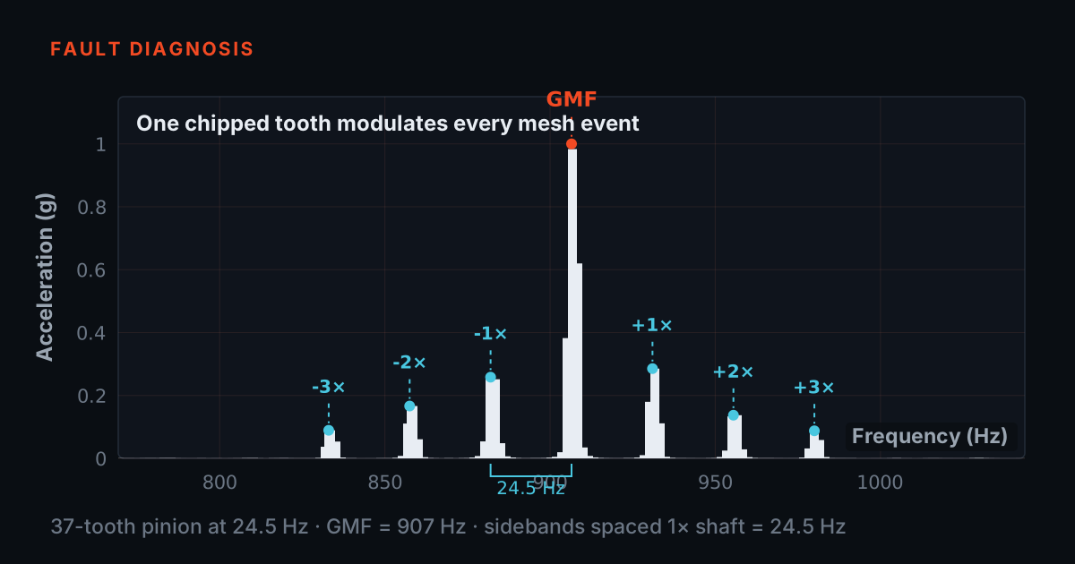
Now chip one tooth on the pinion. For most of each revolution the mesh is healthy and the tone is steady — but once per pinion revolution the damaged tooth carries the load, the contact stiffness dips, and the mesh vibration momentarily jumps and shifts. The gearbox is still singing at the GMF; the defect is rhythmically squeezing that song, once every turn of the shaft the bad tooth rides on. In signal terms, the mesh tone has become amplitude- and phase-modulated at that shaft's rotational frequency.
Modulation in time has an exact signature in frequency: sidebands. The spectrum keeps its carrier peak at the GMF and grows a family of smaller peaks at GMF ± 1, 2, 3… times the modulating frequency — and the modulating frequency is the rotational speed of whichever shaft carries the damaged gear. Chip a pinion tooth and the sidebands sit at shaft-input spacing; chip a gear tooth and they crowd in at the slower output-shaft spacing. The spacing is the fingerprint.
Drive it: the gear-mesh sideband explorer
Set the tooth counts and the input speed, and the simulator does the arithmetic live: GMF = pinion teeth × input shaft frequency, output shaft speed = input × (pinion teeth ÷ gear teeth), and the readouts update as you drag. The spectrum is drawn from those same numbers — every peak sits exactly where the formulas put it, on a full-span view above and a zoom around the mesh peak below.
The severity slider grows a local defect on one tooth, and the two buttons choose which gear carries it. Watch what changes and what does not: the mesh peak itself barely moves, while the sideband family around it grows with severity — and when you move the fault from pinion to gear, the family keeps its shape but its spacing collapses from input-shaft speed to the slower output-shaft speed. The annotated Δ on the zoom plot is the number an analyst would read off with a sideband cursor.
The spacing names the guilty shaft
- Name the shaft and you have named the gear — which means you know which spare to have on the shelf before the case is opened.
- Sideband work is a resolution problem before it is an interpretation problem: a quick snapshot cannot show a family it never resolved.
- Once the lines are there, a sideband cursor does the reading — anchor it on the mesh peak, set the spacing to a candidate shaft speed, and see which family the markers land on.
Run the numbers for our example gearbox both ways. With the 23-tooth pinion chipped, the sidebands sit at 565.4 ± 24.6 Hz — at 540.8 and 590.0 Hz, then 516.3 and 614.6, marching outwards at input-shaft spacing. With one tooth of the 91-tooth gear chipped instead, the same mesh peak wears a much tighter family: 565.4 ± 6.2 Hz, at 559.2 and 571.6. Same carrier, same GMF, completely different verdict. The height of the mesh peak told you nothing either time; the spacing of its escort named the shaft — and with the shaft named, you know which gear to pull and inspect.
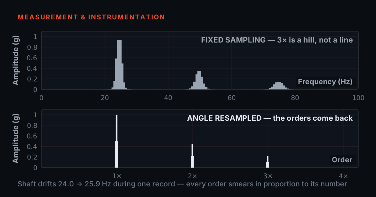
There is a practical catch: to read a 6.2 Hz spacing you must first resolve it. FFT line spacing is one over the capture time, so a 6.2 Hz spacing needs a record of at least 1 ÷ 6.2 ≈ 0.16 seconds merely to land the two peaks in different bins — and one bin apart is not readable. A window's main lobe is several bins wide, so you want the spacing to cover several lines: a one-second record gives 1 Hz lines, which puts six of them between the carrier and its first sideband and makes the family legible; a four-second record gives 0.25 Hz lines and makes it unambiguous. That is why gearbox work leans on long records and high line counts rather than quick snapshots. Once the resolution is there, a sideband cursor does the reading for you: anchor it on the mesh peak, set the spacing to a candidate shaft speed, and see which family the markers land on.
A representative case — and where to practise
A representative example, not a specific customer: a single-stage reduction gearbox on a conveyor drive shows a mesh peak that has drifted upwards over three monthly readings. On height alone the finding is ambiguous — load had also changed. A zoomed spectrum around the GMF settles it: a clean sideband family has appeared, and the spacing matches the output shaft's rotational frequency, not the motor's. The wheel is pulled at the next planned stop and one tooth face shows spalling at mid-flank. The lesson is the sequence: the drifting peak raised the question, but the sideband spacing answered it — which shaft, therefore which gear, therefore which spare to have on the shelf before opening the case.
Pattern recognition like this builds fastest on faults you can trust. A TMFSS simulator's fault library includes gearbox faults among its 30+ conditions, with VFD speed control and a built-in tachometer — so you can seed a known gear fault, sweep the speed, and watch the GMF and its sidebands move exactly as the arithmetic predicts. For the theory, the free Bearing & Gear Analysis 101 primer at 101.tieraonline.in walks through mesh frequencies and sideband families step by step — it is a free primer, not an accredited ISO certification. When you want the formal credential, TIERA's TCAT programme runs structured analyst training (see /services), with proctored examinations conducted at exams.tieraonline.in.
TIERA instruments that do this work.

PhonoVibe Series — Sound & Vibration DAQ
Separating a 6 Hz sideband spacing from a 565 Hz carrier takes long, clean records with dynamic range to spare — 24-bit capture keeps small sidebands above the floor next to a large mesh peak.
- ADC resolution
- 24-bit
- Sampling (Q / O / HD)
- 128 kHz
- Bandwidth (Q / O / HD)
- 0.5 Hz – 60 kHz
- Sensor power
- 24 V, 4 mA (IEPE/ICP/CCLD)
- Sampling
- Simultaneous on every input

TVIB — Sound & Vibration Analysis Software
Its sideband cursor is exactly the Δ annotation from the simulator above, laid over your own spectrum — zoom around the GMF, read the spacing, name the shaft.
- FFT size
- Up to 102,400 points
- Cursors
- Harmonic, band, sideband
- Base module
- TSAP201 — free with PhonoVibe
- OS
- Windows 10 / 11 (32-bit or 64-bit)

TMFSS — Machinery Fault Signature Simulator
Seed a known gearbox fault, sweep the speed with the VFD, and watch the GMF and its sideband families move exactly as the arithmetic predicts — pattern practice against a known truth.
- Faults (Macro)
- 30+ base kit, extensible with add-on kits
- Speed control
- VFD with WiFi software
- Tachometer
- Built-in, analog output
- Foundation
- Solid rigid base
- Warranty
- 1 year; AMC available
From the TIERA store
The kit for this job
What we would actually put in front of someone doing the measurement this post describes — not the whole catalogue.
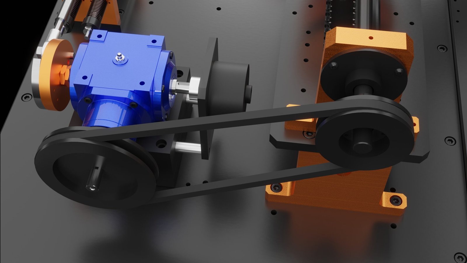 Gear Fault AttachmentGear Fault Attachment for the TMFSS Macro simulates gear-related faults in industrial machinery₹7,12,500View →
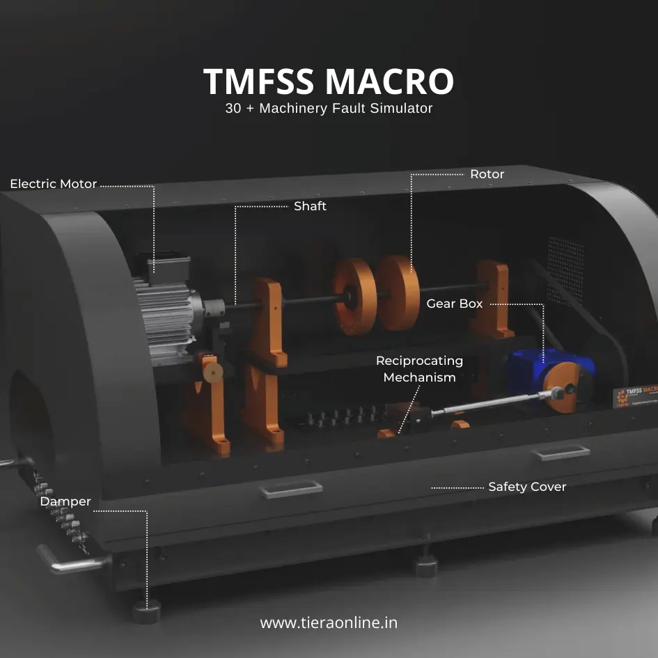 Machinery Fault Signature SimulatorTiera’s Machine Fault Simulator (TMFSS) is a valuable tool for industries and researchers, simulating over 30 real-world faults such as: Bearing faults: outer race defects, inner race defects, cage defects. Motor faults: stator faults, rotor faults, electrical unbalance. Gearbox faults: gear wear, misalignment, gear tooth damage. And more.₹13,53,600View →
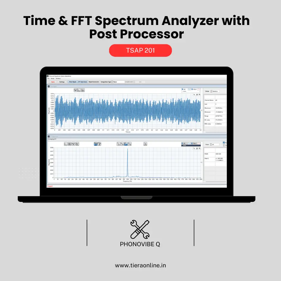 TSAP 201 -Time & FFT Spectrum Analyzer with Post Processor (Phonovibe Q)Use Cases Bump Test Product Development Off route Machine Vibration analysis. Drop Test Product Development & Research₹34,560View →
Use cases
Where this shows up in the field
Resolve the sidebands, then name the shaft with confidence
Sideband work is a resolution problem before it is an interpretation problem: a 6 Hz spacing next to a 565 Hz carrier only appears if your capture is long enough and your FFT fine enough to separate the lines. PhonoVibe Q, O and HD record at 128 kHz sampling with 24-bit resolution across a 0.5 Hz – 60 kHz bandwidth, with IEPE sensor power built in — clean, long records with the dynamic range to keep small sidebands above the floor next to a large mesh peak. Every PhonoVibe ships with TVIB TSAP201, whose FFT runs up to 102,400 points with harmonic, band and sideband cursors — the sideband cursor is exactly the Δ annotation from the simulator above, laid over your own data — and recorded signals can be re-processed later as the picture develops.
If you want the pattern in your hands before a real gearbox provides it, the TMFSS simulator reproduces gearbox faults among its 30+ controlled conditions, with VFD speed control and a built-in tachometer, so an analyst can practise reading GMF and sideband spacing against a known truth.
- PhonoVibe Q / O / HD — 24-bit, 128 kHz sampling, 0.5 Hz – 60 kHz bandwidth, IEPE sensor power, simultaneous sampling on every input
- TVIB TSAP201 (free with every PhonoVibe) — FFT up to 102,400 points with harmonic, band and sideband cursors, plus signal recording and post-processing
- TMFSS — gearbox faults in a 30+ fault library, VFD speed control and built-in tachometer for known-truth practice
Where this sits on the TIERA learning ladder.
The theory behind this article is covered free, in full, by the TIERA 101 primers: Bearing & Gear Analysis 101. They are self-paced, interactive, and end in an exam and a certificate.
TCAT adds structured analyst training with proctored examinations at exams.tieraonline.in — the free 101 primers cover the theory, TCAT certifies you can apply it.
TIERA 101 is a free introductory primer, not an accredited ISO certification, and its hours do not count towards the formal training ISO 18436 requires.