Building a Controlled Machinery Fault Library with TMFSS
A visual mini-explainer: how a lab reproduces unbalance, misalignment, looseness, bearing defects and gear faults on demand, and why a label you set before capture beats a label you guess afterwards.
A label you set beats a label you guess
- Field data is labelled weeks after capture from an ambiguous teardown, and that label noise puts a hard ceiling on any model graded against it.
- Install the fault first and the label exists before the signal does. That is the only version of ground truth worth training anybody — or anything — on.
Field vibration data gets its label weeks after capture, from a work order or a teardown, and teardowns are ambiguous: a bearing run to failure shows spalling, cage damage and lubrication distress all at once. Nobody can say which signature the old recording actually contains. That label noise misleads trainees and puts a hard ceiling on any machine-learning model graded against it.
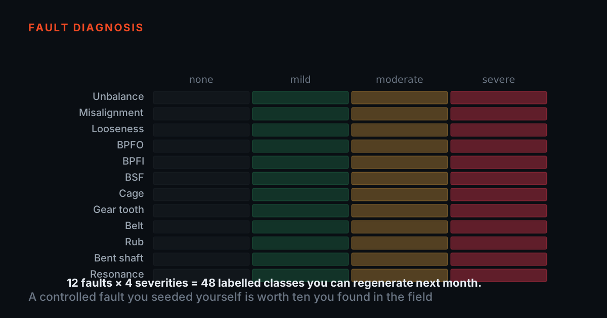
A fault simulator reverses the order: install a known, documented fault first, then capture. The TMFSS Macro reproduces more than 30 rotating-machinery fault conditions on a rigid base, so Tuesday's signature matches Monday's, and each fault ships with a technical note on the physics and expected spectrum. The label exists before the signal does.
Unbalance, misalignment, looseness: three shapes of spectrum
- The diagnosis is the selectivity, not the height: unbalance grows the 1x line while 2x and 3x stay quiet, so broadband growth is not unbalance.
- Parallel and angular misalignment answer in different places — 2x radial against a strong 1x axial — which is why they are worth running as separate configurations rather than one blended fault.
Unbalance is the cleanest case: a heavy spot produces a rotating force at exactly one times running speed (1x), radial, growing with the square of speed. On the rig you step trial mass up and watch only the 1x line climb while 2x and 3x stay quiet; that selectivity is the diagnosis, because broadband growth is not unbalance.
Misalignment answers differently: parallel offset raises 2x radially, angular misalignment adds a strong 1x axial component, and the TMFSS runs each as a separate configuration so trainees see them unblended. Looseness breaks the clean-sinusoid picture entirely, as once-per-revolution impacts grow a long comb of harmonics, sometimes with half orders, and a visibly clipped time waveform.
Bearing defects and gear faults: the non-synchronous story
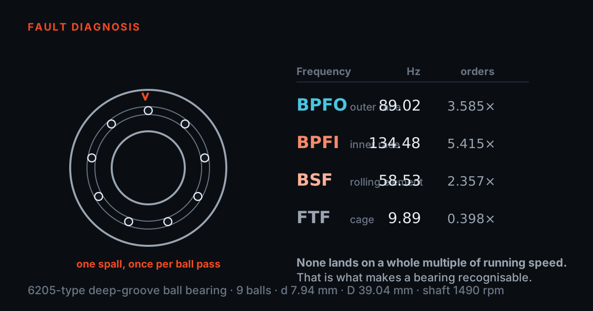
Rolling-element bearing defects appear at frequencies fixed by geometry (BPFO, BPFI, BSF, FTF), never on a neat integer order, and early defects are tiny impacts best read in an envelope spectrum rather than the raw FFT. The TMFSS base library covers all four defect classes, and an accelerated-bearing-wear add-on kit lets you capture a staged degradation sequence instead of a binary good-or-bad pair.
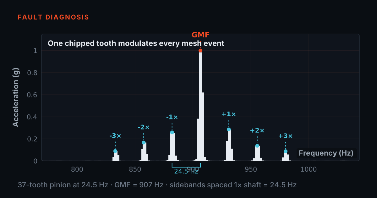
Gears concentrate their story around the gear mesh frequency (tooth count times shaft speed). One damaged tooth disturbs the mesh once per revolution of its own shaft, throwing up sidebands spaced at exactly that shaft's speed, so the spacing names the faulty shaft, and the sideband growth — not the mesh line — tracks severity.
The capture chain: speed, phase and clean metadata
Two rig features carry the acquisition discipline. The Macro's VFD with WiFi control software repeats an exact speed grid run after run, and the built-in tachometer's once-per-revolution analogue output is the phase reference that makes order tracking, synchronous averaging and balancing exercises possible.
PhonoVibe DAQs sample every channel simultaneously at 24-bit, power IEPE, ICP and CCLD sensors (24 V, 4 mA) and read TEDS, so cross-channel phase between a bearing sensor and the tach survives intact; every unit carries a factory calibration certificate. In TVIB, the free TSAP201 module adds FFT up to 102,400 points, harmonic, band and sideband cursors, and acceleration-to-velocity-to-displacement integration, with acquisition settings saved alongside each recording.
Case study: a representative fault-library build
- Spend day one entirely on healthy baselines, with repeats. Every later comparison leans on them, and nothing recovers a baseline you did not take.
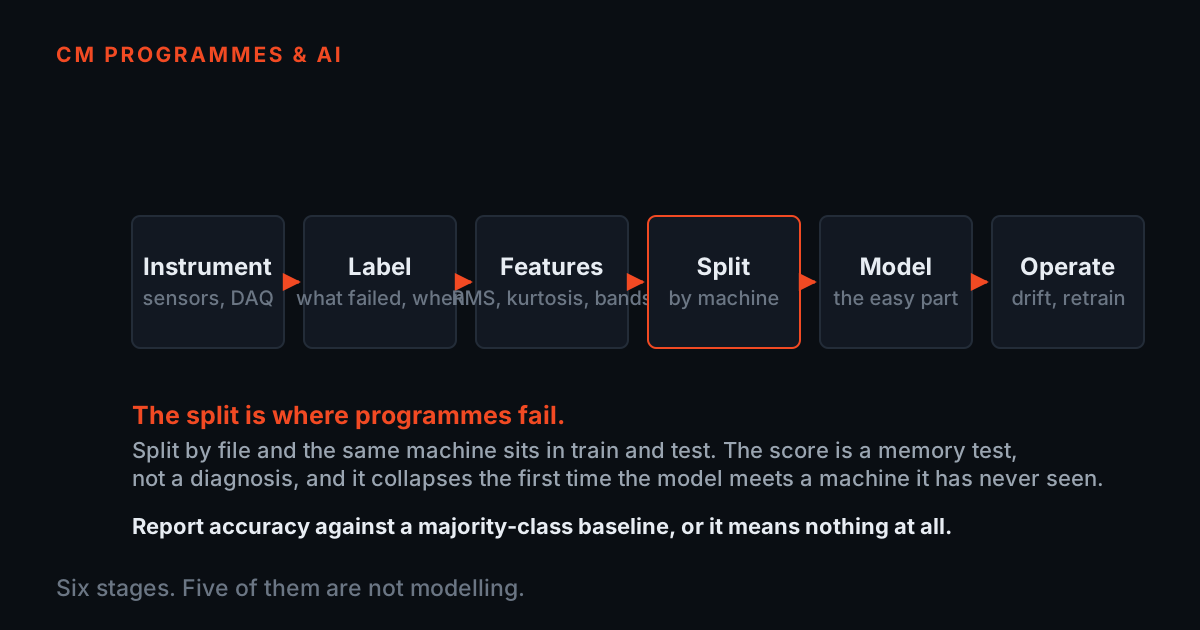
- Withhold selected speeds and severity steps. Without hold-out conditions you can only report how well a model remembers, not how well it works.
A representative lab workflow, not a specific customer: a reliability group wants a labelled in-house library before rolling out condition monitoring. Day one is spent entirely on healthy baselines across four speeds, with repeats, because every later comparison leans on them. Days two to four introduce one fault at a time from the Macro library, each run across the same speed grid, and nothing is captured until the fault, speed, sensor set-up and settings are written into the run record.
Day five withholds selected speeds and severity steps as hold-out data, so later algorithms and trainees can be tested on conditions they have not seen. The deliverable is not a headline accuracy number; it is an audited library where every record answers what was wrong, how badly, at what speed, and how it was measured.
From simulator time to certified analysts
The theory behind every figure above is covered in the free TIERA 101 primers at 101.tieraonline.in; they are primers, not an accredited certification. When a team needs formal, recognised competence, the TCAT programme, aligned with ISO 18436-2 Category I to IV, adds instructor-led depth, assessed practicals on simulator hardware, and proctored examinations on exams.tieraonline.in, with details on the services page at tieraonline.in/services.
The natural sequence for a new lab: read the primers, put every analyst through structured simulator hours on the fault set they will meet in the field, and let those carrying diagnostic responsibility sit the appropriate TCAT categories. The simulator turns theory into pattern recognition; certification makes that recognition accountable.
TIERA 101 primers
Free theory primers on vibration fundamentals and fault signatures. No certification, no cost.
101.tieraonline.inSimulator hours on TMFSS
Structured practicals: reproduce each fault, capture it, read it, repeat it until recognition is automatic.
TMFSS familyTCAT Cat I–IV
ISO 18436-2 aligned training with formal assessment, examined on TIERA's proctored platform.
TCAT programme exams.tieraonline.inTIERA instruments that do this work.
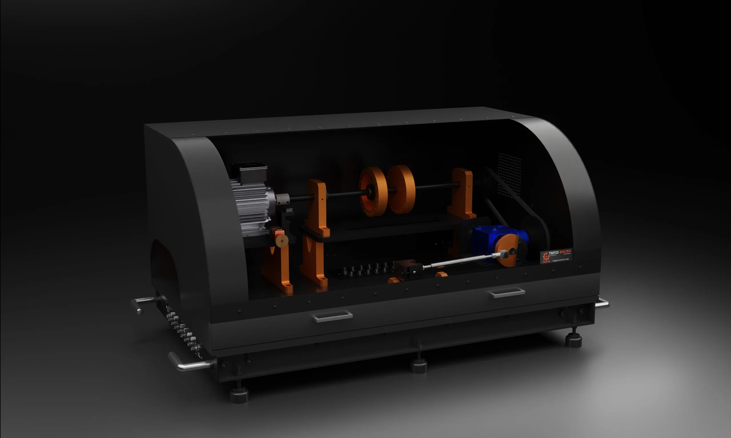
TMFSS Macro — Full-Industry Machinery Fault Simulator
The fault source for the library: 30+ seeded fault conditions on a rigid base, so the label exists before the signal is captured and Tuesday's signature matches Monday's.
- Faults (base kit)
- 30+, expandable with add-on kits
- Speed control
- VFD with WiFi control software
- Tachometer
- Built-in, analog output
- Foundation
- Solid rigid base
- Warranty
- 1 year; AMC available

PhonoVibe Series — Sound & Vibration DAQ
The capture chain: simultaneous 24-bit sampling and a factory calibration certificate per unit make every recording in the library defensible.
- ADC resolution
- 24-bit
- Sampling
- Simultaneous on every input
- Sensor power
- 24 V, 4 mA (IEPE/ICP/CCLD)
- TEDS
- Supported
- Calibration
- Factory certificate, 1-year validity

TVIB — Sound & Vibration Analysis Software
Turns each capture into a labelled spectrum: harmonic, band and sideband cursors to verify every seeded fault shows the signature its technical note predicts.
- FFT size
- Up to 102,400 points
- Base module
- TSAP201 — free with PhonoVibe
- OS
- Windows 10 / 11 (32-bit or 64-bit)
- Licence
- Perpetual; 2 years free updates
From the TIERA store
The kit for this job
What we would actually put in front of someone doing the measurement this post describes — not the whole catalogue.
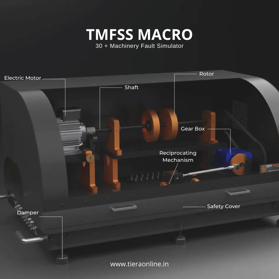 Machinery Fault Signature SimulatorTiera’s Machine Fault Simulator (TMFSS) is a valuable tool for industries and researchers, simulating over 30 real-world faults such as: Bearing faults: outer race defects, inner race defects, cage defects. Motor faults: stator faults, rotor faults, electrical unbalance. Gearbox faults: gear wear, misalignment, gear tooth damage. And more.₹13,53,600View →
- Machinery Fault Signature Simulator | TMFSS MINIThe TMFSS Mini is Tiera’s compact yet powerful machinery fault simulator designed to provide hands-on learning and experimentation in fault diagnosis and vibration analysis. Ideal for educational institutions, research labs, and professionals, the TMFSS Mini enables users to simulate real-world machinery faults in a controlled environment.Request priceView →
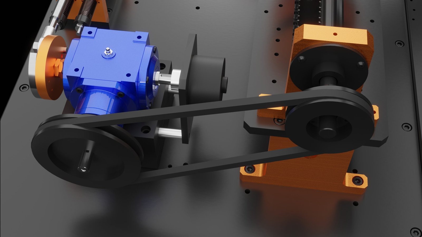 Gear Fault AttachmentGear Fault Attachment for the TMFSS Macro simulates gear-related faults in industrial machinery₹7,12,500View →
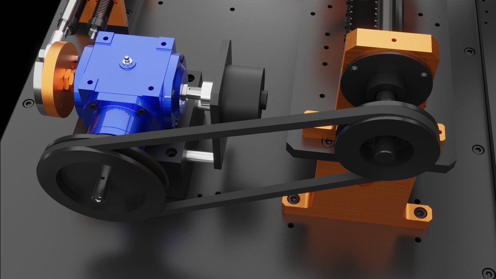 Belt drive fault simulation kitBelt Drive Fault Simulation Kit for the TMFSS Macro replicates belt drive faults in industrial machinery.₹2,25,000View →
 Resonance Simulation KitResonance Faults Addon Kit for the TMFSS Macro simulates resonance-related faults in industrial machines₹1,87,500View →
Use cases
Where this shows up in the field
Build the labelled fault library your analysts and models are missing
Every stage of the workflow above is equipment TIERA designs, builds and supports from Thiruvananthapuram. The fault source is the TMFSS Macro: 30-plus rotating-machinery fault conditions on a rigid base, each shipped with a technical note on the physics and the expected spectrum, with add-on kits — bent shaft, finned rotor, accelerated bearing wear, lockable bearing, mechanical rub — to grow the library over time. The Mini (7+ faults) and classroom-format Micro cover training labs that do not need the full research rig.
The capture chain is the PhonoVibe DAQ series and the TVIB TSAP 201 software bundled free with it, so the phase reference, acquisition settings and calibration record that make a library defensible are handled by the same toolchain that recorded it. Tell us the faults your team needs to recognise and we will spec the rig, the channel count and the training path around them.
- TMFSS Macro — 30+ fault conditions with VFD speed control (WiFi software) and a built-in tachometer with analogue output, so every run repeats the same speed grid with a phase reference
- Add-on kits extend the base library: bent shaft, finned rotor, accelerated bearing wear, lockable bearing and mechanical rub
- PhonoVibe DAQs (2 to 16 channels) — 24-bit, simultaneous sampling on every input, IEPE/ICP/CCLD sensor power with TEDS, factory calibration certificate with each unit
- TVIB TSAP 201, bundled free with every PhonoVibe — FFT up to 102,400 points, harmonic/band/sideband cursors, and acceleration-to-velocity-to-displacement integration
Where this sits on the TIERA learning ladder.
The theory behind this article is covered free, in full, by the TIERA 101 primers: Vibration 101 (Foundations), Machinery Fault Diagnosis 101. They are self-paced, interactive, and end in an exam and a certificate.
TCAT adds ISO 18436-2 aligned Category I to IV training on top of the free primers: instructor-led depth, assessed practicals on simulator hardware, and proctored examinations at exams.tieraonline.in.
TIERA 101 is a free introductory primer, not an accredited ISO certification, and its hours do not count towards the formal training ISO 18436 requires.