Hazardous-Area Vibration Sensing: Zones, Not Divisions
An Indian plant is classified in zones. A great deal of the instrumentation offered to it is described in divisions. Buying across that gap is one of the most expensive procurement errors in condition monitoring — and it is entirely avoidable once you can read a marking string field by field. A decoder you can drive, and a straight account of why intrinsic safety is a property of the loop rather than of the sensor.
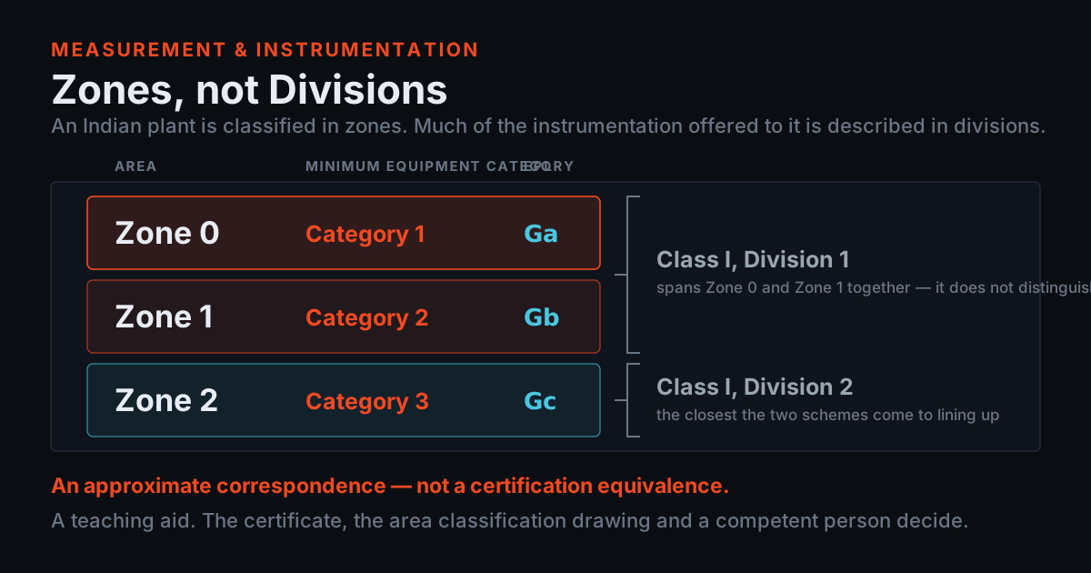
Zones, not divisions
- An Indian plant is classified in ZONES. A great deal of the instrumentation offered to it is described in DIVISIONS. Both schemes are real; they are not interchangeable strings on a purchase order.
- Division 1 spans Zone 0 and Zone 1 together, so a Division 1 certificate does not tell you which of the two the equipment was assessed against.
- TIERA's judgement: use the correspondence to READ a drawing or catalogue written in the other scheme, never to SIGN one. If your area is classified in zones, the acceptable evidence is a certificate in the zone scheme.
Start with the sentence that matters most on this page, before anything else. This page is a teaching aid and nothing more: it is never a substitute for the equipment certificate, the area classification drawing, or the judgement of a competent person, and no decoder — including this one — can make an installation safe. Everything below is written to make you better at reading the documents, and worse at trusting a label instead of them.
With that said: an Indian plant is classified in ZONES. The area classification drawing for a refinery, a fertiliser plant, a sugar mill or a cement works divides the place into zones — 0, 1 and 2 for gas, 20, 21 and 22 for dust — and specifies what may be installed in each. That is the IEC scheme, it is what the Indian standards are built on, and it is what your safety department will ask you for.
A great deal of the instrumentation offered to those plants is described in DIVISIONS, because North America classified that way first and the catalogues followed. Class I Division 1, Class I Division 2, Class II Division 1. Both schemes are real, both are rigorous, and both are still in daily use — the North American products in this catalogue are genuine products for genuine plants, not legacy stock. What they are not is interchangeable strings on a purchase order.
Here is how the error actually happens, and it almost never looks like carelessness. A buyer with a Zone 1 requirement is offered a Class I Division 1 accelerometer. Division 1 sounds like the most stringent thing on offer, because it is the most stringent thing in ITS scheme. The order is signed. The equipment arrives, and at the pre-commissioning check somebody asks for the ATEX or IECEx certificate that the zone-classified area needs — and there isn't one, because the part was never certified in that scheme. Nothing is defective. Nothing was mis-sold. The equipment is simply documented in a language the site's paperwork cannot accept.
The table below sets the two schemes side by side. The zone definitions, the equipment category each zone needs and the protection level each zone needs are DEFINITIONAL: they belong to the standard, and the category and protection-level columns are computed here by the same functions the decoder at the foot of this page runs, so no cell in them was typed by hand. The last column is the approximate correspondence — and it is worth saying plainly what "approximate" is doing there. Division 1 spans Zone 0 AND Zone 1 together, so a Division 1 certificate does not tell you which of the two the equipment was assessed against. Only Zone 2 and Division 2 come close to lining up, and even they are not a certification equivalence.
It is TIERA's engineering judgement that the useful way to hold all this is: use the correspondence to READ a drawing or a catalogue written in the other scheme, and never to SIGN one. If your area is classified in zones, the acceptable evidence is a certificate in the zone scheme. Many parts carry both — a great many CTC accelerometers are certified under CSA in the division scheme and under IECEx and ATEX in the zone scheme simultaneously, and the model tables on their store pages state both — and where that is true the problem simply does not arise. Where it is not true, no amount of correspondence-table reasoning fixes it.
The zone scheme is what an Indian plant is classified in. The zone definitions, the category each zone needs and the equipment protection level each zone needs are definitional — they belong to the standard, not to TIERA. The category and protection-level columns below are computed from the same functions the bench at the foot of this page runs, so no cell in them was typed. The final column is the approximate correspondence with the North American division scheme. It is there so you can read a drawing or a catalogue written in the other scheme. It is not a certification equivalence, and it is TIERA's engineering judgement that treating it as one is the single most expensive mistake in this whole subject.
| Zone | When the atmosphere is there, and where you meet it | Category needed | Protection level | Approximately, in divisions |
|---|---|---|---|---|
| Zone 0 gas |
An explosive gas atmosphere is present continuously, for long periods, or frequently. Inside a tank or a vapour space; immediately around an open vent. |
Category 1 zone 0, 1, 2 |
Ga | Class I, Division 1 Division 1 spans Zone 0 and Zone 1 together — it does not distinguish them. |
| Zone 1 gas |
An explosive gas atmosphere is likely to occur in normal operation, occasionally. Around seals, sample points and loading gantries; the pump and compressor houses most CM programmes care about. |
Category 2 zone 1, 2 |
Gb | Class I, Division 1 Division 1 spans Zone 0 and Zone 1 together — it does not distinguish them. |
| Zone 2 gas |
An explosive gas atmosphere is not likely in normal operation and, if it does occur, persists only briefly. The wider process area around Zone 1 sources; most of a refinery's outdoor plot. |
Category 3 zone 2 |
Gc | Class I, Division 2 The closest thing in the scheme to a one-to-one correspondence, and still not a certification equivalence. |
| Zone 20 dust |
A combustible dust cloud is present continuously, for long periods, or frequently. Inside silos, hoppers, mills, cyclones and filter housings. |
Category 1 zone 20, 21, 22 |
Da | Class II, Division 1 The dust divisions map onto the dust zones the same approximate way the gas ones do. |
| Zone 21 dust |
A combustible dust cloud is likely to occur in normal operation, occasionally. Around discharge points, bag-tipping stations and access hatches. |
Category 2 zone 21, 22 |
Db | Class II, Division 1 The dust divisions map onto the dust zones the same approximate way the gas ones do. |
| Zone 22 dust |
A combustible dust cloud is not likely in normal operation and, if it does occur, persists only briefly. The wider handling area; the floor around a Zone 21 source where layers settle. |
Category 3 zone 22 |
Dc | Class II, Division 2 The dust divisions map onto the dust zones the same approximate way the gas ones do. |
Reading the label
A marking string looks like line noise until you know it is eight fields written in a fixed order. Take the one this post works from: II 1 G Ex ia IIC T4 Ga. Read left to right, it says: group II, surface industry rather than mining; category 1; a gas atmosphere; the Ex mark; protection concept ia, which is intrinsic safety, two-fault; gas group IIC; temperature class T4; and equipment protection level Ga.
Three of those eight decide which zone the thing may enter, and they are the three drawn in orange in the figure. The category is the big one: category 1 equipment covers zone 0, zone 1, zone 2, category 2 equipment covers zone 1, zone 2, and category 3 equipment covers zone 2 and nothing else. The G or D says which ladder you are on at all. The protection level is the same statement written a second way — Ga for zone 0, Gb for zone 1, Gc for zone 2 — and its presence on a modern marking is a useful cross-check against the category.
The other five fields are not decoration. The protection concept says HOW the equipment is protected, and it changes what the installation has to do: an ia sensor needs a barrier and a loop calculation, a flameproof enclosure needs its own certified glands and every bolt in place. The gas group says which atmospheres the equipment was built for, and it is nested — IIC covers IIC, IIB, IIA — so hardest at the top, and never the other way round. The temperature class has a section of its own further down because it is the field people read backwards.
Case is load-bearing, and this is worth more attention than it usually gets. ia in lower case is a protection concept. Ga with a capital is an equipment protection level. They are different fields carrying different information, and a marking transcribed into an email in the wrong case has genuinely lost data. The decoder at the foot of this page is deliberately case-sensitive for that reason: a lower-case string does not decode, and that is the honest answer rather than a bug.
Dust markings are a parallel, not an afterthought. II 2 D Ex tb IIIC T135°C Db reads the same way: group II, category 2, a dust atmosphere, protection concept tb — protection by enclosure, dust — dust group IIIC, a maximum surface temperature written out as T135°C rather than as a T-class, and protection level Db. Category 2 dust equipment covers zone 21, zone 22. In sugar, grain, cement and coal handling, the dust ladder is the one that matters and the gas one is irrelevant — and a sensor marked for one is not marked for the other, whatever else is right about it.
One thing the string does not tell you, and it is the most important omission: whether there are SPECIAL CONDITIONS OF USE. Those are flagged by an X after the certificate number — not on the marking string at all — and they are conditions, not footnotes. TIERA's engineering judgement, from what we see at audit, is that the X is the single most commonly ignored character in this whole subject.
Every field of II 1 G Ex ia IIC T4 Ga, in the order it is written. The decoder at the foot of this page reads exactly these fields out of whatever you type into it — and reports the ones it cannot find as absent rather than guessing them.
| Field | Name | What it says |
|---|---|---|
| II | Equipment group | Surface industry. Group I is mining equipment for firedamp and is a different world. |
| 1 | Equipment category | How much of the time the maker built it to survive an explosive atmosphere. This is the field that decides the zone. |
| G | Atmosphere | G is gas, vapour or mist. D is dust. A sensor marked for one is not marked for the other. |
| Ex | The Ex mark | Says the rest of the string is an explosion-protection marking. Not a field with a value. |
| ia | Protection concept | HOW it is protected — here, intrinsic safety with two-fault tolerance. This is a property of the whole loop, not of the sensor alone. |
| IIC | Gas group | Which atmospheres it is built for. IIC is the hardest — hydrogen and acetylene — and covers IIB and IIA as well. |
| T4 | Temperature class | Maximum SURFACE temperature, 135 °C. Not an ambient rating, and a higher T number is a colder surface. |
| Ga | Equipment protection level | What is left when things go wrong: a is two-fault, b is one-fault, c is normal operation. Case matters — Ga is a level, ia is a concept. |
Definitional, and nested the way people find counter-intuitive. The group says how easily the atmosphere ignites, so the hardest group covers the easier ones and not the other way round. The "covers" column is computed by the same function the bench runs, for every pair, so it cannot be typed wrongly. Gas groups and dust groups never substitute for one another.
| Group | Family | Reference atmosphere | Covers areas classified |
|---|---|---|---|
| IIC | Gas | Hydrogen and acetylene — the hardest to contain | IIC, IIB, IIA |
| IIB | Gas | Ethylene | IIB, IIA |
| IIA | Gas | Propane | IIA |
| IIIC | Dust | Conductive dust | IIIC, IIIB, IIIA |
| IIIB | Dust | Non-conductive dust | IIIB, IIIA |
| IIIA | Dust | Combustible flyings | IIIA |
Intrinsic safety is a property of the loop, not of the sensor
- The certified thing is the LOOP: a certified barrier or galvanic isolator on the safe side, a certified sensor on the hazardous side, and a cable between them whose capacitance and inductance are part of the calculation.
- 2 of the 5 entity-parameter comparisons bring the cable in, which is why an intrinsically safe loop has a maximum cable length — a number that falls out of two certificates rather than a rule of thumb.
- The unit of purchase is therefore the loop: sensor, barrier, cable type, cable length, and the calculation that ties them together.
This is the section that earns the post, and it is the misunderstanding that costs the most money after the zone-versus-division one.
An accelerometer marked ia is not, on its own, intrinsically safe. It cannot be. Intrinsic safety is the principle that the circuit never holds enough energy to ignite the atmosphere — not in normal operation, and not with faults present. A sensor sitting in a drawer holds no energy at all. The moment you connect it to something, the question becomes what that something can push down the cable, and the answer has nothing to do with the sensor.
So the certified thing is the LOOP: a certified barrier or galvanic isolator on the safe side, a certified sensor on the hazardous side, and a cable between them whose capacitance and inductance are part of the calculation. CTC's own store page for the barriers puts the function plainly: "The primary function of the barrier is to limit the electrical energy supplied to accelerometers or proximity probes located in hazardous areas, ensuring that sparks, heat, or faults cannot ignite an explosive atmosphere." The IECEx loop-power sensor family says the same thing from the other end — its features list reads "Requires Energy Limiting Barriers such as IS111-1B" — and the hazardous-area 11 mm proximity probe page carries the note "Class 1 Division 1/Zone 1 systems require the use of an intrinsically safe barrier, such as IS151-1B". Three product pages, one message: the sensor is half a system.
The comparison that has to come out right is called an entity-parameter check, and there are five inequalities in it. Uo ≤ Ui, Io ≤ Ii, Po ≤ Pi, Ci + Cc ≤ Co, Li + Lc ≤ Lo. The first three compare what the barrier can put out against what the sensor may be given. The last two are the ones that catch people out, because they bring the cable in: the sensor's own capacitance plus the CABLE's capacitance must stay under what the barrier can drive, and the same for inductance. Cable capacitance is a function of length, so an intrinsically safe loop has a maximum cable length, and it is a number that falls out of two certificates rather than out of a rule of thumb.
Three consequences follow, and all three are things TIERA has watched go wrong on real sites. Re-routing an IS cable to a longer path is a design change, not a site decision — the loop calculation has to be redone. Splicing in a length to reach a relocated junction box does the same thing. And swapping a barrier for a different model because the original had a long lead time invalidates every one of the five comparisons at once, even if the replacement is a perfectly good barrier from a perfectly good manufacturer.
The practical upshot for a condition-monitoring programme is that you cannot buy hazardous-area sensors the way you buy ordinary ones. The unit of purchase is the loop: sensor, barrier, cable type, cable length, and the calculation that ties them together. When TIERA quotes a hazardous-area point, that is what is being quoted — and if a supplier will sell you an ia accelerometer without ever asking what it will be connected to, that tells you something useful about the supplier.
The comparison is called an entity-parameter check, and it is arithmetic on numbers that come from documents. Two of the five bring the cable in, which is why an intrinsically safe loop has a maximum cable length and why re-routing one later is a design change rather than a site decision.
| Must hold | Quantity | From the barrier certificate | From the sensor certificate | From the cable |
|---|---|---|---|---|
| Uo ≤ Ui | Voltage | Uo — the most the barrier can put out | Ui — the most the sensor may be given | — not involved |
| Io ≤ Ii | Current | Io — the most the barrier can push | Ii — the most the sensor may be given | — not involved |
| Po ≤ Pi | Power | Po — the most the barrier can deliver | Pi — the most the sensor may be given | — not involved |
| Ci + Cc ≤ Co | Capacitance | Co — the most capacitance the barrier can drive safely | Ci — the sensor's own capacitance | Cc — the cable's capacitance, which is length × the figure on the cable spec |
| Li + Lc ≤ Lo | Inductance | Lo — the most inductance the barrier can drive safely | Li — the sensor's own inductance | Lc — the cable's inductance, also a function of length |
Temperature class is about the surface, not the ambient
- The ladder runs backwards from the way people read it: T1 is 450 °C and T6 is 85 °C, so the numbers go UP while the temperature goes DOWN. A higher T number is a colder surface and a STRICTER requirement.
- The surface has to stay below the ignition temperature of whatever is actually in the air at that point — a figure that comes from the area classification, not from a sensor catalogue and not from this page.
- An ambient rating and a temperature class are different things measured at different places. A datasheet's operating temperature range has told you nothing about the temperature class.
The temperature class is a maximum SURFACE TEMPERATURE that the equipment may reach — including under the fault conditions its certificate assessed. T4 means the surface stays below 135 °C. T3 means it stays below 200 °C. The requirement exists because a hot surface will ignite an explosive atmosphere with no spark involved at all, so the equipment's surface has to stay below the ignition temperature of whatever is actually in the air at that point — a figure that comes from the area classification, not from a sensor catalogue and not from this page.
The ladder runs backwards from the way people read it, and that is the whole of the misreading. T1 is 450 °C and T6 is 85 °C, so the numbers go UP while the temperature goes DOWN. A higher T number is a colder surface and therefore a STRICTER requirement. T6 equipment satisfies a T1 area comfortably; T1 equipment does not go anywhere near a T6 one. Every time somebody reads "T3" as better than "T4" because three is a smaller and therefore tighter-sounding number, an order goes out for the wrong part.
The bench demonstrates it with the chip labelled "T3 equipment where the area asks T4". The marking is II 2 G Ex d IIC T3 Gb and the area is Zone 1 · IIC · T4. Zone, category, group and protection level all pass. The temperature class fails, because 200 °C is above the 135 °C the area allows, and the decoder returns "refused". Nothing else about that sensor is wrong.
The second confusion in this field is between the temperature class and the ambient temperature rating, and they are different things measured at different places. An ambient rating says the range of air temperatures the equipment is designed to work in; a temperature class says how hot its own surface is allowed to get. A sensor whose datasheet says it operates from −20 to 80 °C has told you nothing about its temperature class. Both matter, and the certificate states the temperature class AT a stated ambient range — go outside that range and the certificate simply does not apply, whatever the label on the case says.
Dust adds a third temperature that is easy to miss. For dust atmospheres the marking states a temperature in degrees rather than a T-class, and a dust LAYER on the equipment insulates it, so the permitted surface temperature depends on how deep the layer is allowed to get. That is a housekeeping requirement dressed up as an instrumentation one, and it is a genuine reason why dust-zone sensors and their enclosures get specified together with a cleaning regime rather than on their own.
Decode a marking
Here is the decoder. Type or paste a marking into the box, choose the area you intend to install it in, and it will split the string into its eight fields, work out which zones that category may enter, and compare the group, the temperature class and the protection level against the area. The chips load the cases this post discusses, so you can reproduce every example above rather than taking it on trust.
Before you use it: This page is a teaching aid and nothing more: it is never a substitute for the equipment certificate, the area classification drawing, or the judgement of a competent person, and no decoder — including this one — can make an installation safe. The bench carries the same warning permanently on its own face, so that a screenshot of it cannot travel without the caveat attached.
It is deliberately asymmetric about what it will say, and that asymmetry is the honest part. It can return "refused", which means at least one field it can check does not line up, and that is a real finding: stop, and go back to the certificate. It can return "undecidable", which means the string does not carry enough to decide. It can return "consistent", which does NOT mean suitable — it means the marking is worth taking to the certificate, and nothing further. Certification, the special conditions of use, the ambient range, the loop and the area classification drawing all live outside anything a string can tell you.
Two of the chips come back "undecidable" on purpose, and they are the two most realistic strings on the bench. "The marking a supplier actually sent" loads II 2 G — a category that does cover the zone, and silence on the gas group and the temperature class. Silence is not permission. And "A North American Division marking" loads Class I Division 1 Groups A B C D T4, which this decoder returns "undecidable" for because it cannot read it at all — it is written in the other scheme. That is not a gap in the tool. It is the post's thesis, demonstrated: the two schemes are not the same string with different words in it, and the answer to a division marking on a zone-classified site is a certificate, not a translation.
The chip worth clicking twice is "A IIB sensor in a hydrogen (IIC) area". The marking is II 2 G Ex ib IIB T4 Gb, the area is Zone 1 · IIC · T4, and the zone is right, the category is right, the temperature class is right and the protection level is right. It still comes back "refused", because IIB equipment does not cover a IIC atmosphere. This is the expensive failure mode: everything on the purchase order looks correct, and the mismatch is in a three-character field nobody checked.
And one chip saves money rather than spending it. "Zone 2 outdoor plot, ic sensor" is category 3 equipment in a zone 2 area, which is the right answer there. Most of a plot is zone 2. Specifying category 1 kit for a zone 2 point buys no additional safety and costs real money, and over-specification is as much a failure of engineering as under-specification — it is simply a failure nobody gets blamed for.
A pump house on an ethylene-class duty. The commonest Zone 1 a CM programme meets.
The commonest Zone 1 job in condition monitoring, correctly specified. Category 2 covers zone 1, IIB matches, and T4 is a colder surface than the T3 the area asks for.
What this decoder does: it splits the string into the eight fields above, works out which zones that category may enter, and compares the group, the temperature class and the protection level against the area you chose. It is deliberately asymmetric. It can show you that a marking is INCONSISTENT with an area, which is a reason to stop. It can never show you that equipment is suitable, because suitability lives in the certificate, in the special conditions of use marked by an “X” after the certificate number, in the ambient range, in the loop, and in an area classification drawing this page has never seen. Case matters: ia is a protection concept and Ga is a protection level, so a marking typed in lower case will not decode — which is the honest answer, not a bug. This page is a teaching aid and nothing more: it is never a substitute for the equipment certificate, the area classification drawing, or the judgement of a competent person, and no decoder — including this one — can make an installation safe.
What changes for the installer
Choosing the right part is roughly half the job. The other half happens on site, and it is where a correctly specified hazardous-area installation most often stops being one.
Cable glanding comes first, because it is the most visible and the most often wrong. A certified enclosure is certified WITH a specified gland arrangement, not with any gland that fits the hole. The gland has to match the protection concept and the cable's construction — armoured, braided or plain — and an ordinary industrial gland fitted to an Ex e terminal box because it was what was on the van has voided the certificate before the lid goes back on.
Earthing is next, and for intrinsic safety it is a system requirement rather than a good-practice one. The barrier needs its dedicated intrinsically safe earth, continuous and correctly sized, to the barrier's earth bar. Landing it on the nearest convenient panel stud produces a loop that is not the loop the certificate describes, and no inspection of the sensor end will ever reveal it.
Then the paperwork, which is the part that decides whether any of the above survives an audit. The cable length has to be recorded, because the loop calculation depends on it. IS wiring has to be segregated and identified — its own gland plate, its own route, light-blue identification — and not run in a shared multicore because there were spare cores in it. Junction boxes have to be certified and their certificate numbers recorded against the tag. And the X after a certificate number has to be read, acted on and recorded as having been read.
The dossier that ties it together is a short list and it is worth writing down before the work starts rather than after: the certificate for every certified item, a photograph of every marking as installed, the loop calculation, the cable schedule with lengths, the gland schedule, and the revision of the area classification drawing the design was done against. TIERA's engineering judgement is that the commonest audit finding on Indian sites is not wrong equipment at all. It is correct equipment, correctly installed, with nothing written down — and at that point it has to be proved again from scratch.
Last, treat the classification drawing as a live document rather than a background fact. Areas get reclassified when a process changes, a vent moves or a new unit goes in next door. Equipment that was correct for zone 2 on the day it was installed is not automatically correct after a reclassification, and a condition-monitoring programme that quietly accumulates sensors over five years is exactly the kind of asset register that drifts out of step with the drawing. Re-checking it is cheap. Discovering it at an audit is not.
- Fit the gland arrangement the enclosure is certified with, matched to the protection concept and to the cable's construction
- Run the barrier's dedicated intrinsically safe earth, continuous and correctly sized, to the barrier's earth bar
- Record the cable length, because the loop calculation depends on it
- Segregate and identify IS wiring — its own gland plate, its own route, light-blue identification
- Read the X after a certificate number, act on it, and record that it was read
- Fit an ordinary industrial gland to a certified enclosure because it was what was on the van
- Land the IS earth on the nearest convenient panel stud
- Run IS wiring in a shared multicore because there were spare cores in it
- Use an uncertified junction box, or leave its certificate number unrecorded against the tag
- Treat the area classification drawing as a background fact — areas get reclassified when a process changes
The left two columns are what the protection concept requires. The right-hand column is TIERA's engineering judgement about what actually goes wrong on Indian sites — it is what we see at commissioning and at audit, not a survey and not a statistic. None of it replaces the installation standard, the certificate's special conditions, or a competent person signing the work off.
| What changes | What the concept requires | What goes wrong (TIERA's judgement) |
|---|---|---|
| Cable glanding | Certified glands, correct to the enclosure's protection concept and to the cable's construction — armoured, braided or plain. | A standard gland fitted to an Ex e box because it was what was on the van. The certificate covers the enclosure with ITS glands, not with any gland. |
| The barrier's earth | A dedicated intrinsically-safe earth to the barrier's earth bar, sized and continuous, separate from the instrument screen earth unless the certificate says otherwise. | The barrier is landed on the nearest panel earth stud. The loop then is not the loop the certificate describes. |
| Cable parameters | The cable's capacitance and inductance per metre, times the installed length, recorded and compared with the barrier's Co and Lo. | Nobody records the length. A drum change or a re-route later makes the loop non-compliant and there is no document that would show it. |
| Segregation | IS wiring kept separate from non-IS wiring, in its own gland plate, its own trunking route and light-blue identification. | A shared multicore because there were spare cores in it. |
| Junction boxes | Certified enclosures with a certified terminal arrangement, and the certificate number recorded against the tag. | An uncertified box in a Zone 2 area on the grounds that Zone 2 is 'the easy one'. |
| The special conditions | An 'X' after the certificate number means there ARE special conditions of use. Read them and record that you read them. | The X is treated as a suffix rather than as an instruction. It is the single most common documentation finding TIERA sees. |
| The dossier | Certificate, marking photograph, loop calculation, cable schedule, gland schedule and the area classification drawing revision the design was done against. | Everything above is done correctly and none of it is written down, so at the next audit it has to be done again. |
TIERA instruments that do this work.
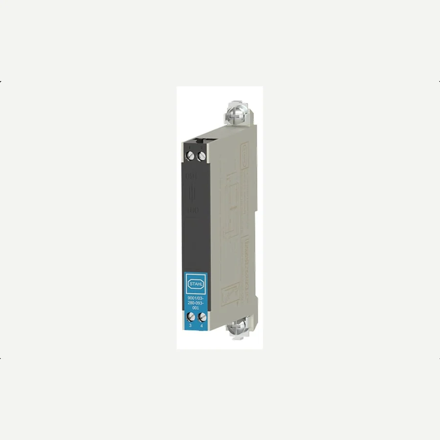
CTC IS Series Intrinsically Safe Barriers — IS111-1B and IS151-1B
The component that makes the argument in this post concrete. Its store page states the function exactly: to limit the electrical energy supplied to accelerometers or proximity probes located in hazardous areas, so that sparks, heat or faults cannot ignite an explosive atmosphere. Buy the sensor without it and you have bought half a loop — which is why both the loop-power sensor family and the hazardous-area proximity probe sets name these part numbers in their own pages.
- IS111-1B
- Barrier for use with Class 1, Division 1/Zone 0,1 sensors
- IS151-1B
- Barrier for use with PRO proximity probe drivers with voltage output
- Part numbers in family
- 2
- Supply
- TIERA, authorised CTC distributor in India
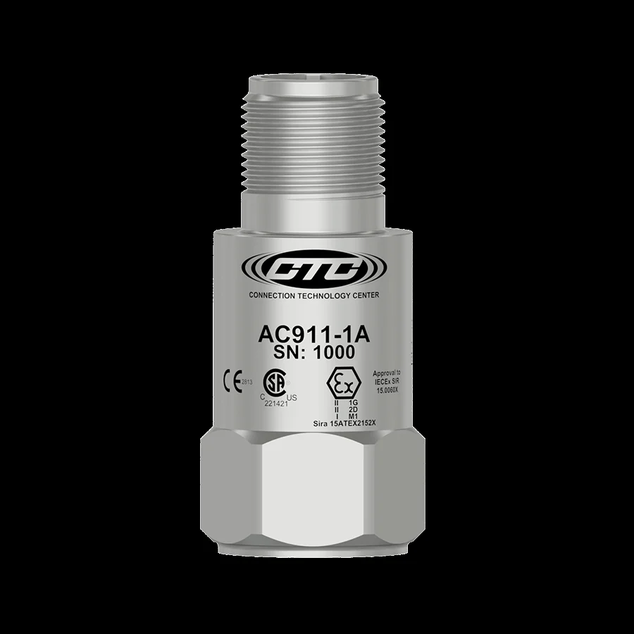
CTC IECEx Zone 0,1 Approved Sensors
The zone-scheme range, for areas where an explosive atmosphere is present continuously or is likely in normal operation. The model table on the store page states each part's approvals in full, and a great many of them carry the North American division approvals alongside the IECEx and ATEX zone ones — which is the situation in which the zone-versus-division problem this post describes simply does not arise. Read the row for the part number you are quoting; the approvals differ between them.
- Part numbers in family
- 24
- Types
- Standard, miniature, biaxial, triaxial, dual output, 4-20 mA loop power
- Case material
- 316L stainless steel
- Transverse sensitivity
- ≤5%
- Calibration certificate
- CA10
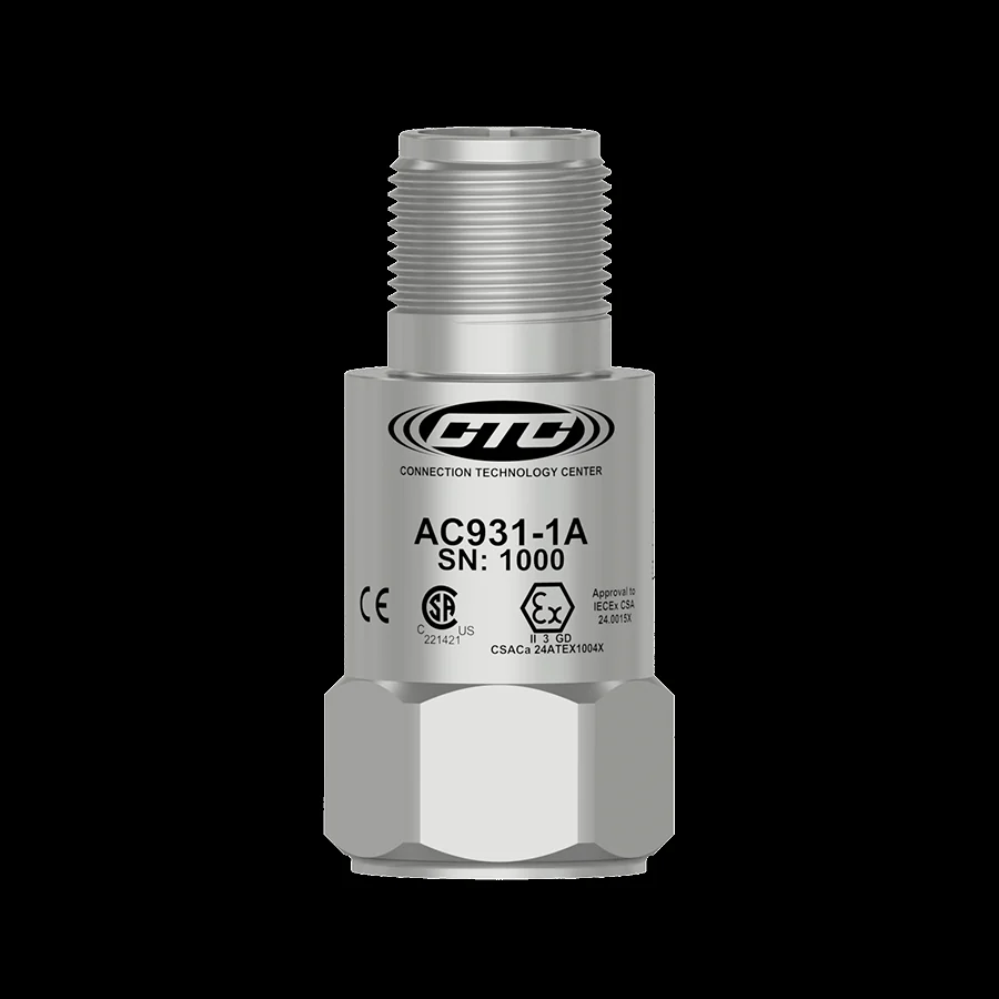
CTC ATEX Zone 2 Approved Sensors
The chip on the bench that saves money. Most of a process plot is Zone 2, and this is the range built for it — the store page describes a nonincendive design intended for settings with intermittent exposure to hazardous gases. Specifying a Zone 0,1 part for a Zone 2 point buys no additional safety and costs real money. Check the model table for the exact approvals on the part number you want, and check them against your own area classification drawing.
- Part numbers in family
- 15
- Types
- Standard top and side exit, miniature, biaxial, triaxial, dual output, velocity
- Excitation
- 2-10 mA constant current
- Case material
- 316L stainless steel
- Calibration certificate
- CA10
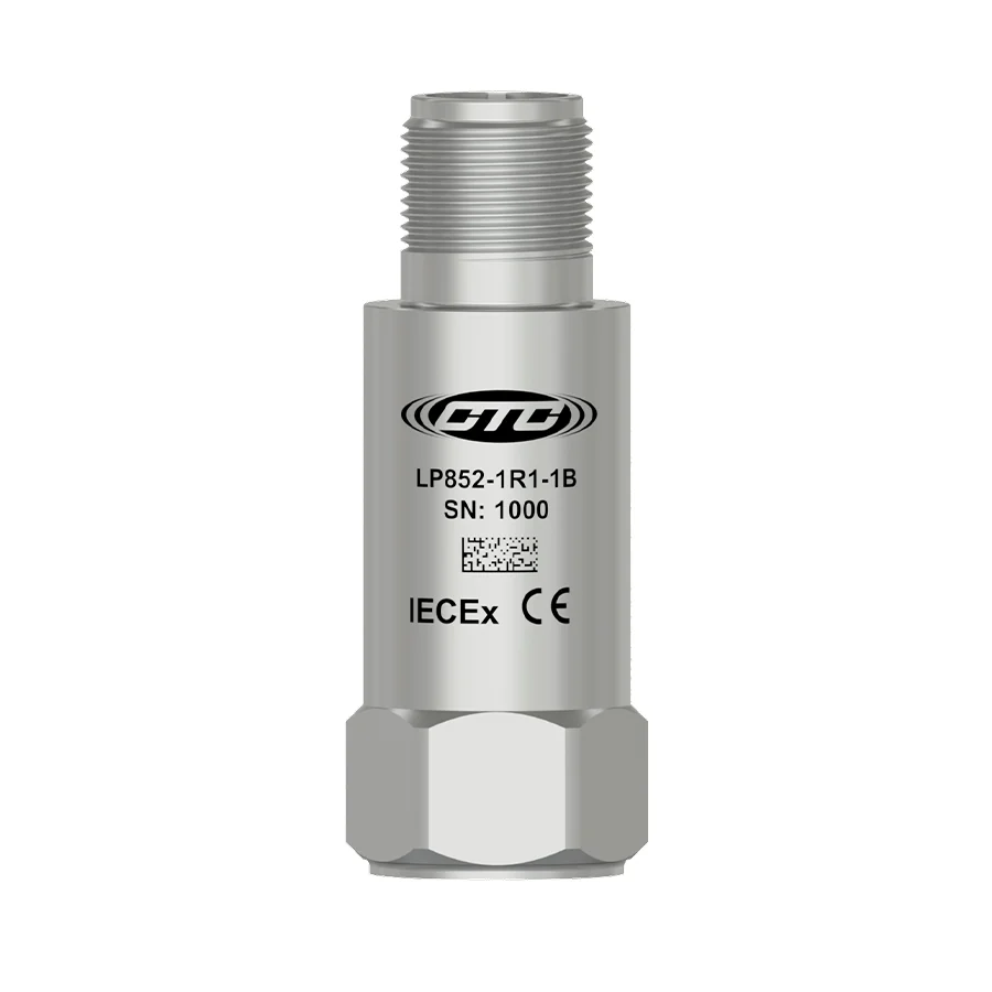
CTC Intrinsically Safe IECEx Loop Power Sensors
A 4-20 mA output proportional to vibration in velocity or acceleration, which is the format a DCS or PLC already accepts — and the family whose own features list says, in those words, that it requires energy-limiting barriers such as the IS111-1B. It is the clearest illustration in the catalogue that the loop is the unit of purchase, not the sensor.
- Part numbers in family
- 8
- Output
- 4-20 mA, velocity or acceleration
- Voltage source
- 12-28 VDC
- Operating temperature range
- −20 to 80 °C
- Sealing
- Welded, hermetic
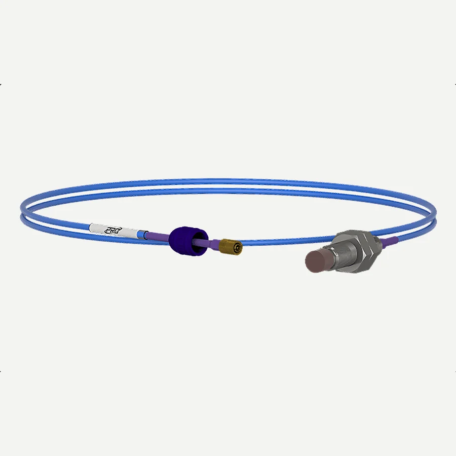
CTC 11 mm Hazardous-Area Approved Proximity Probe Sets
Shaft displacement on fluid-film-bearing machines in a hazardous area — turbines, large compressors, the machines where API 670 protection is the requirement rather than a route measurement. The store page states the optional hazardous-area certifications and carries the note that Class 1 Division 1/Zone 1 systems require the use of an intrinsically safe barrier, such as the IS151-1B. Probe, extension cable and driver are quoted together because that is the only way this measurement exists.
- Probe
- 11 mm eddy-current proximity probe system
- Standard
- Compliant with API 670
- Gap range
- 20 to 180 mils
- System lengths
- 1 m, 5 m and 9 m
- Barrier
- Class 1 Division 1/Zone 1 systems require an IS barrier such as IS151-1B
From the TIERA store
The kit for this job
What we would actually put in front of someone doing the measurement this post describes — not the whole catalogue.
- BarriersCTC IS Series intrinsically safe barriers help ensure safety and compliance in hazardous industrial environments. An intrinsically safe barrier is a critical component in condition monitoring systems in hazardous areas where flammable gases, vapors, or dust are present.Request priceView →
- IECEx Zone 0,1 Approved SensorsCTC's IECEx Zone 0,1 approved accelerometers are expertly engineered for environments where explosive atmospheres are present continuously or intermittently during normal operations.Request priceView →
- ATEX Zone 2 Approved SensorsCTC’s ATEX Zone 2 hazardous-rated accelerometers are engineered for industrial settings with intermittent exposure to hazardous gases and are certified under the ATEX directive for European and international markets.Request priceView →
- Intrinsically Safe IECEx — Intrinsically Safe IEC Certified (IECEx) Loop Power SensorIntrinsically Safe IEC Certified (IECEx) Loop Power Sensor, 4-20 mA Output Proportional to Vibration in Velocity, Top Exit 2 Pin ConnectorRequest priceView →
- 11 mm Hazardous-area Approved Proximity Probe SetsCTC proudly offers 11 mm proximity probe systems, also known as eddy current probe systems, with optional hazardous area certifications, including Class 1 Division 1/Zone 1 and Class 1, Division 2.Request priceView →
Use cases
Where this shows up in the field
Tell us the zone, and we will quote the loop rather than the sensor.
TIERA is the authorised CTC distributor in India, and the hazardous-area range — zone-scheme and division-scheme, gas and dust, accelerometers, velocity sensors, loop-power transmitters, proximity probe systems and the intrinsically safe barriers that go with them — is the part of the catalogue where getting the paperwork right matters more than getting the price right.
What that means in practice: send us the area classification for the point, the marking you have been offered if you have already been offered one, and the cable route. We will come back with the part numbers, the approvals as the manufacturer states them, the barrier, and what the loop needs. Where we cannot support a certification claim from the manufacturer's own documents, we will tell you that instead of quoting around it.
- Zone-scheme and division-scheme parts, with the approvals quoted as the model tables state them — never paraphrased into the other scheme.
- Intrinsically safe barriers specified with the sensor, because the loop is the unit that gets certified.
- Dust zones treated as a first-class case: sugar, grain, cement and coal handling, not an afterthought to the gas ranges.
- The awkward answer where it applies: if the certificate does not exist in the scheme your site is classified in, we will say so.
Where this sits on the TIERA learning ladder.
The theory behind this article is covered free, in full, by the TIERA 101 primers: Accelerometer & DAQ Selection 101, Measurement Setup 101. They are self-paced, interactive, and end in an exam and a certificate.
The primers cover the sensor and the measurement chain. Hazardous-area classification itself is not a vibration subject and TIERA does not teach it as one — the competent-person judgement this post keeps pointing at comes from the standards and from your own safety function, and the right next step is your area classification drawing and the certificates for the parts you are considering.
TIERA 101 is a free introductory primer, not an accredited ISO certification, and its hours do not count towards the formal training ISO 18436 requires.