


Wiring a 64-Channel Test: Junction Boxes, Ground Loops, and Channel Discipline
Below about eight channels, cabling is an afterthought. Above thirty it becomes the dominant risk in the test: a mains hum you cannot explain, a channel map nobody trusts, and a day lost to a connector that was never seated. The fixes are boring, cheap and almost always skipped.
What changes when the channel count goes up
A four-channel measurement is four cables you can see at once. You know which is which because you can follow them with your eyes. If one is loose you will find it in seconds.
A sixty-four-channel modal survey is a different activity. You cannot see the whole harness, you cannot trace a cable by eye, and a single mis-assigned channel silently corrupts a mode shape in a way that looks like physics rather than like an error. Meanwhile you have sixty-four shields, sixty-four possible ground paths and a structure that is probably earthed somewhere of its own.
Three problems dominate at this scale, and they are worth naming precisely because each has a different fix: ground loops (electrical), channel mapping (bookkeeping) and mechanical reliability of connections (physical). Nothing else comes close in terms of hours lost.
The ground loop, and why it shows up as 50 Hz you cannot kill
Your DAQ is earthed through its mains supply. The machine under test is earthed through its own supply, at a different point in the building. Those two earth points are not at exactly the same potential — they never are, because current flows in building steel and neutral conductors and produces small voltage differences between anything nominally at zero volts.
Now run a shielded cable from a sensor mounted on the earthed machine back to the earthed DAQ. If the shield connects to ground at both ends, you have made a loop: a closed conducting path enclosing an area, sitting in a building full of alternating magnetic fields. Current flows around that loop, and because the shield is also the signal return, that current appears in your measurement as mains-frequency hum and its harmonics.
The symptoms are recognisable: a stubborn peak at 50 Hz (or 60 Hz) with harmonics, that gets worse with longer cables, changes when you move the harness, and that no amount of averaging removes — because it is a genuine deterministic signal, not noise.
The fix is to break the loop, and the rule is ground the shield at one end only — normally the DAQ end. Then the shield still does its job as an electrostatic screen but no longer offers a closed path for current. Where that is not sufficient, isolated inputs or isolated conditioning break the loop galvanically. What does not work is adding more earth straps, which is the instinctive response and usually makes it worse by creating more paths.
One caution worth stating plainly: a sensor whose case is grounded through its mounting is already earthed to the machine. Insulated mounting studs and adhesive mounting pads exist largely for this reason, and on a big survey they are a cheaper fix than isolated conditioning.
What a junction box is actually for
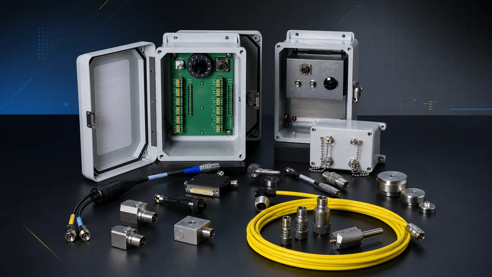
A junction box is often mistaken for a convenience item — somewhere to plug things in. Its real jobs are more specific, and they are what justify building one properly rather than assembling a pile of adaptors.
It moves the cable break to a sensible place. Running sixty individual sensor cables the full distance to the DAQ is expensive, heavy and fragile. Running sixty short cables to a box near the structure, and one multi-core trunk from the box to the DAQ, is cheaper, tidier and far more robust. The trunk is the only long run, and it can be a properly protected one.
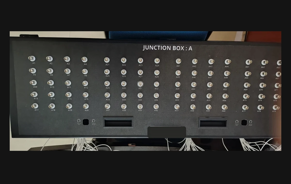
It makes the channel map physical. A box with permanently marked, sequential channel positions is a map you cannot lose. The alternative — labels on cable tails that curl up, fall off or get swapped — is the single most common source of a corrupted mode shape.
It is where grounding policy gets enforced. One place where shield handling is decided and consistent across every channel, rather than sixty independent decisions made by whoever plugged in that cable.
It takes the mechanical abuse. Connectors fail from repeated insertion and from strain. A box gives you strain relief and puts the wear on connectors you can replace, rather than on the DAQ's own front panel.
Channel discipline: the boring practice that saves the day
Adopt a numbering convention before the first sensor goes on, and make it describe location rather than order of installation. Point number, then direction — P12-V, P12-H, P12-A — beats ch37, because ch37 tells you nothing when the shape looks wrong three weeks later.
Record the map as you build it, not afterwards. A photograph of the instrumented structure with the point numbers visible has rescued more surveys than any software feature.
Then verify it before you trust it. Tap each point in turn and confirm the expected channel responds. On a sixty-four-channel survey this takes about ten minutes and it is the highest-value ten minutes of the day: it catches swapped channels, dead channels, wrong axes and unseated connectors in one pass, while everything is still accessible. Do it after the harness is fully dressed, because dressing cables is exactly when connections get disturbed.
Check bias voltage on every channel at the same time if your conditioning reports it. A channel reading at the supply rail is an open circuit, and finding that now costs nothing — finding it in the data costs the whole test.
The pre-test checklist that is worth taping to the box
Shields earthed at one end only, and everyone on the team knows which end. Sensor mounting checked for unintended earthing through the machine. Every channel tap-tested and its bias voltage confirmed. Channel map written down and photographed. Trunk cable routed away from motor drives, VFD cabinets and welding gear — not neatly beside them, which is where cable trays tend to lead. Connectors seated and strain-relieved. Spare cables and one spare sensor within reach, because on a sixty-four-channel test something will fail and the question is only whether it costs you five minutes or the afternoon.
TIERA instruments that do this work.
Custom High-Channel Junction Boxes
Built to your channel count and connector standard, with consistent shield handling and a channel map you cannot lose.
- Build
- Channel count and connectors to order

Armored Vibration Sensor Cable
For the trunk run and for anywhere a cable gets stepped on, which on a plant floor is everywhere.
PhonoVibe HD — 16-Channel IEPE DAQ
Simultaneous sampling across all channels — essential when the whole point is phase between points.
- Channels
- 16, expandable by chaining
From the TIERA store
The kit for this job
What we would actually put in front of someone doing the measurement this post describes — not the whole catalogue.
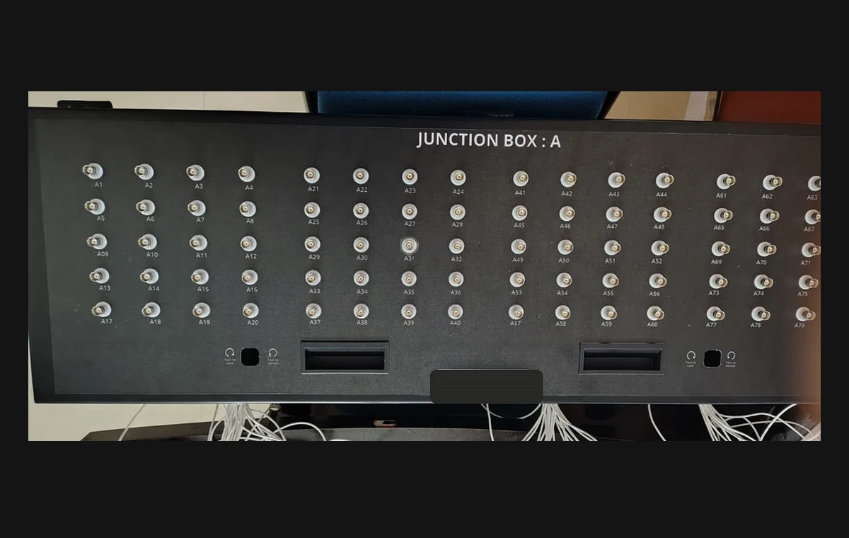 Vibration Monitoring Junction BoxCustom high-channel junction box that consolidates multiple accelerometer / microphone cables into one protected, lockable enclosure — clean zone wiring and a clear channel map for permanent vibration-monitoring and large-array test installations.Request priceView →
- Armored Vibration sensor cableCA-103-5-A : Tinned Copper Braid 2 Core Twisted Shielded Cable with Stainless Steel Outer Armor – One side 2 pin Circular MIL Connector other side Bare wires / BNC Connector₹2,300View →
 16 Channel IEPE Data Acquisition System-Phonovibe HDSixteen-Channel Data Acquisition System Plug & Play USB Powered Compatible with accelerometers, microphones, hammers, and other IEPE sensors T-VIB Software for time waveforms, frequency spectra, vibration levels, FRFs, and octave measurements Base version includes Time and Spectrum with TSAP 201 post-processor Explore additional modules with T-VIB Software₹7,20,000View →
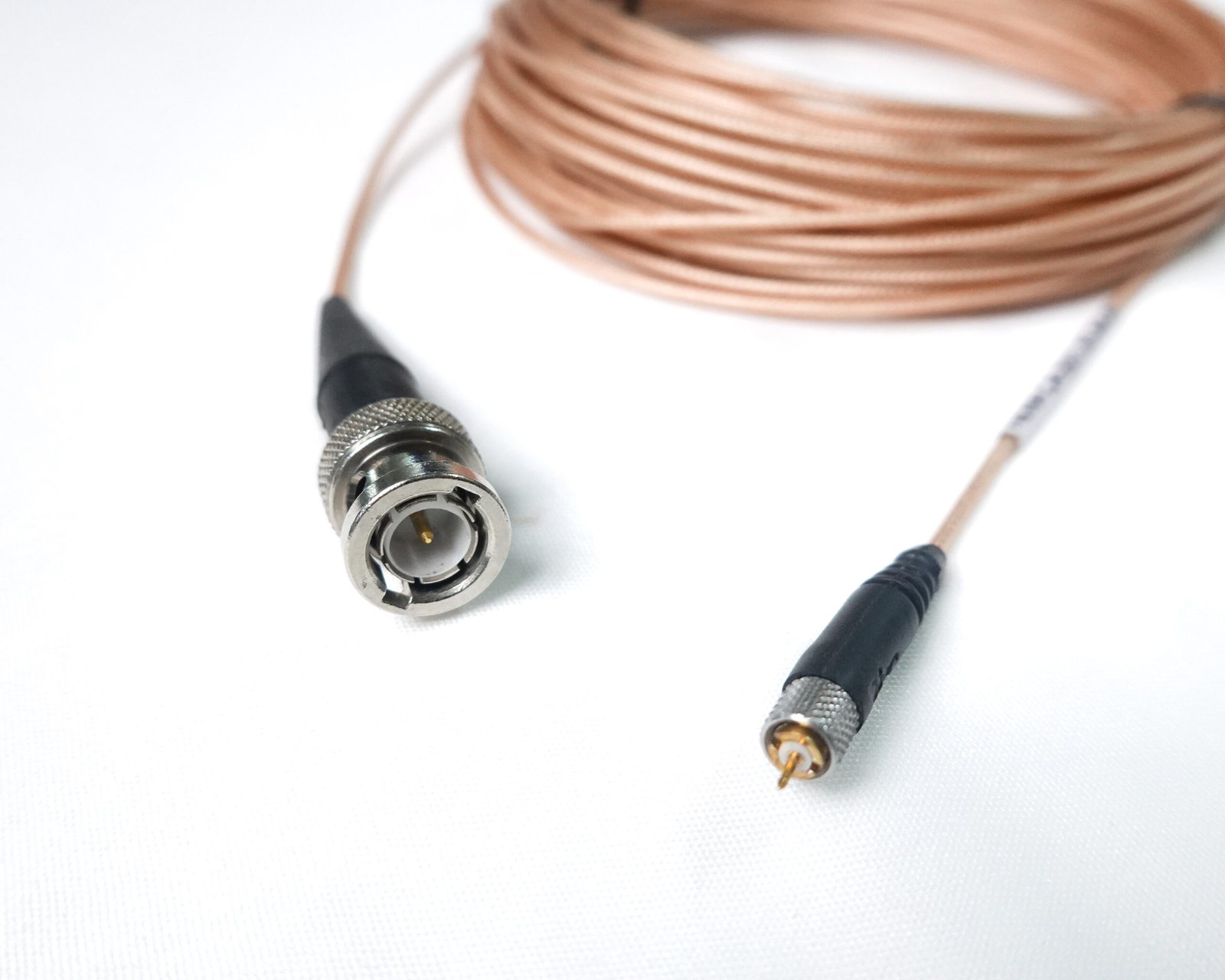 Low-Noise Coaxial Sensor CableCA-101-5-M-B: Low-Noise Tin plated copper braid Coaxial cable – one end 10-32 / M5 Microdot Connector other end BNC Connector₹2,200View →
Use cases
Where this shows up in the field
The harness decides whether a big test is repeatable.
We build junction boxes to the channel count and connector standard you actually use, with the grounding policy decided once and applied to every channel.
If you are scaling from eight channels to sixty, talk to us before you buy cable — the trunk topology is the decision that sets your cost and your noise floor.
- Junction boxes built to order for channel count and connector type
- Trunk and tail cabling specified for the run and the environment
- PhonoVibe HD for simultaneous multi-channel acquisition
Where this sits on the TIERA learning ladder.
The theory behind this article is covered free, in full, by the TIERA 101 primers: Measurement Setup 101, Accelerometer & DAQ Selection 101. They are self-paced, interactive, and end in an exam and a certificate.
The primer covers mounting and the measurement chain. Instrumenting a large structure — channel discipline, grounding strategy and verifying a map before you trust a mode shape — is the practical half of Cat III modal work.
TIERA 101 is a free introductory primer, not an accredited ISO certification, and its hours do not count towards the formal training ISO 18436 requires.