


Planning a Modal Test: The Decisions You Make Before the First Hit
Where you put the reference, how you support the structure, and how many points you measure are decided before any data exists — and they set the ceiling on what the test can possibly tell you. No amount of curve-fitting recovers a mode you put a reference on the node of.
A modal test answers a question you have to ask first
"Do a modal test on this" is not a specification, and a test run against it usually produces data nobody can act on. The plan follows from the question, and there are only a few questions people actually have.
Is this resonance the reason my machine is rough? You need the modes in a narrow band around a known forcing frequency, and you need the shape at the location that is moving. This is a small, focused test.
Will my design survive the environment? You need modes across a wide band, and you need them accurately enough to correlate with a finite-element model. This is a large test with a boundary condition that matches the model.
Where do I add stiffness or damping to fix this? You need shapes with enough spatial resolution to see where the motion actually is — and the answer is usually driven by the shape, not the frequency.
The first question can often be answered with a handful of points and a couple of hours. The second can take a week and sixty channels. Deciding which you are doing is the single most consequential planning step.
Boundary conditions: match the model, or say what you did
A structure's modes depend on how it is held. Change the support and you change the answer — not slightly, fundamentally.
Free-free — the structure hangs on soft bungees or sits on very soft foam, so that the rigid-body modes are far below the first flexible mode. This is the condition most finite-element models are validated against, because it removes the support from the problem entirely. The practical test is that the rigid-body frequencies should be below about a fifth of the first flexible mode; if they are not, the suspension is stiff enough to be part of the structure.
Fixed / in-situ — the structure is bolted down as it will be used. This is the condition that answers operational questions, and it is far harder to reproduce, because a bolted joint's stiffness depends on preload, surface finish and how many times it has been undone. Two nominally identical installations will not give identical modes, and that is a real finding rather than an error.
The failure to avoid is correlating an in-situ test against a free-free model and then arguing about a 12% frequency discrepancy that is entirely the boundary condition. Whatever you choose, record it in enough detail that someone could reproduce it — bungee stiffness, foam type, bolt torque, all of it.
Reference selection: the mistake that cannot be undone
Every FRF is measured relative to a reference — the fixed point, whether that is where you drive (a shaker) or where you fix the response sensor (roving hammer). Every mode shape you extract is scaled by the reference's motion in that mode.
So if the reference sits on a node of a mode — a point that does not move in that shape — then that mode contributes almost nothing to any FRF you measure, and it will be missing from your results. Not noisy. Missing. And there is no processing step that recovers it, because the information was never acquired.
This is the single most common way a modal test fails, and it fails silently: you get a clean dataset with a mode absent, and unless you were expecting that mode you will never know.
The defences are simple and worth making routine. Use a preliminary finite-element model or a quick roving survey to find likely node lines and stay off them. Choose a reference away from symmetry planes, because symmetric structures put nodes exactly there. Where the structure matters enough, use two or more references — a mode nodal at one is very unlikely to be nodal at both, and multi-reference data also lets you detect repeated roots that single-reference data cannot separate at all.
How many points, and where
The number of measurement points does not need to resolve the frequency — it needs to resolve the shape. Too few points and two genuinely different modes look identical, a condition called spatial aliasing, and it is exactly as damaging as its frequency-domain namesake.
The working rule is a minimum of six to eight points per half-wavelength of the highest mode you care about. That sounds abstract until you turn it around: decide the highest mode of interest first, sketch its expected shape, and put enough points on it that the shape is unmistakable.
Two practical additions. Put points at the locations you might actually modify — the bracket you could stiffen, the mass you could add — because a beautiful shape that has no point where the fix goes cannot guide the fix. And where a structure has both bending and torsion in the band, you need points off the centreline, or torsion will simply not appear.
The check afterwards is the Modal Assurance Criterion. Compute the MAC of your shape set against itself: strong off-diagonal terms mean two extracted shapes are not sufficiently distinct, which usually means too few points rather than genuinely repeated modes. It is a five-minute check that tells you whether the geometry you chose was adequate.
Hammer or shaker
A hammer is fast, portable, needs no fixturing and is ideal for a focused question or an in-situ check. Its limits are real: the force input is short and broadband, so the energy at any one frequency is modest, and on a heavily damped or large structure you may simply not excite enough response. Double hits, inconsistent strike location and operator variability all add scatter, and the tip choice sets your usable bandwidth — a soft tip gives more energy but less high-frequency content.
A shaker gives controlled, sustained, repeatable excitation and much better signal-to-noise, which matters for large structures and for accurate damping estimates. The price is setup time, a stinger, a fixture and the possibility of the fixture appearing in your data.
For most R&D questions, plan on a hammer survey to find the modes and understand the structure, then a shaker test for the accurate numbers if the answer needs to be trusted quantitatively.
The checks before you leave the structure
Coherence near one across the frequency band of interest, and if it is not, understand why before you pack up — poor coherence at a resonance is often just low input energy, but poor coherence everywhere is usually a chain problem you can still fix. Drive-point FRF measured and checked for the correct alternating pattern of resonances and antiresonances. Reciprocity spot-checked on at least one pair of points. MAC computed on the extracted shapes. Rigid-body frequencies confirmed low enough if you claimed free-free.
Every one of those is far cheaper to do while the structure is still instrumented than to discover afterwards, which is the whole argument for planning the test rather than just running it.
TIERA instruments that do this work.
Impact Hammer IH-01
The fast route to finding the modes and understanding the structure before committing to a shaker setup.

Miniature Tri-axial IEPE Accelerometer 141A100
Three axes at one point, and light enough that mass loading does not shift the mode you came to measure.
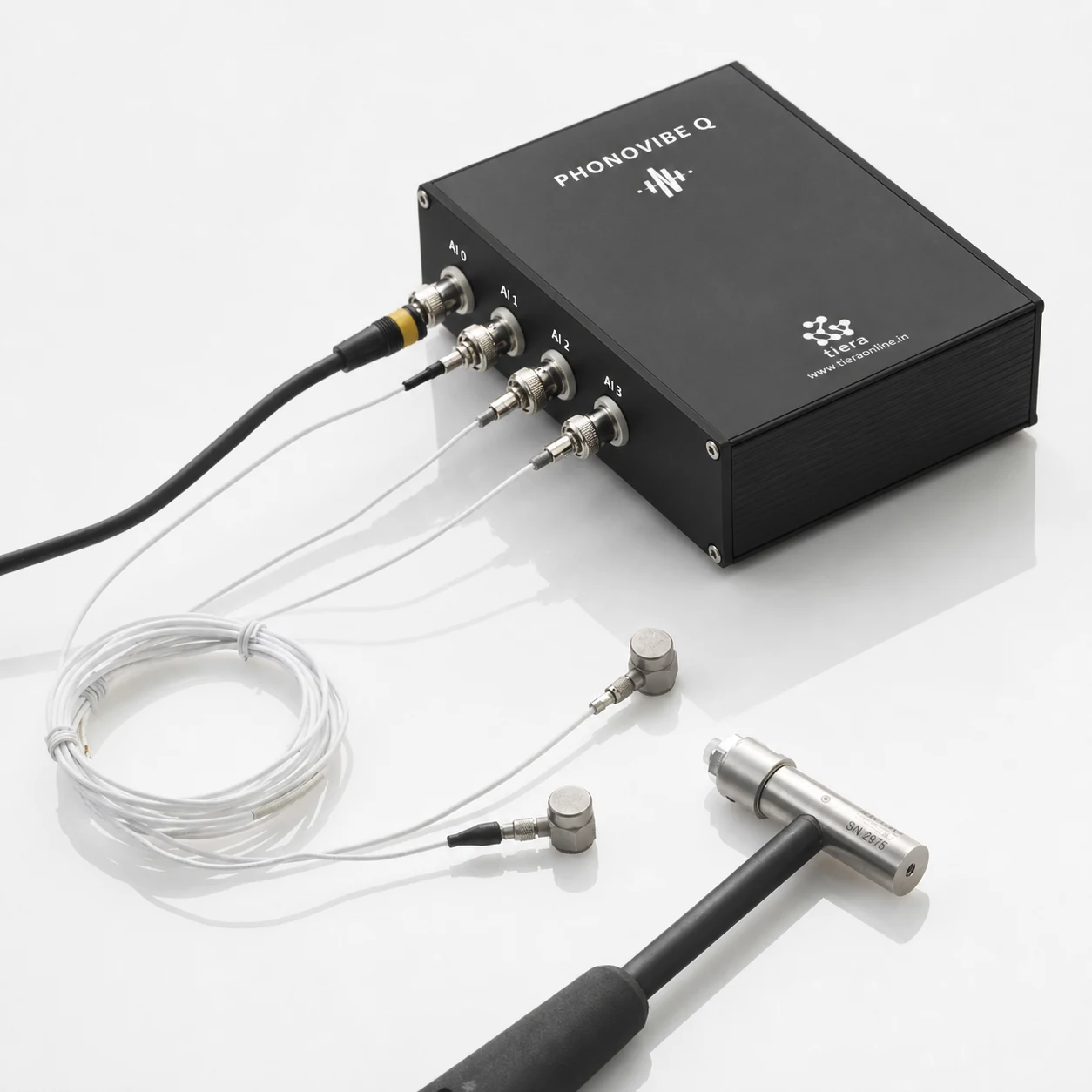
PhonoVibe Q — 4-Channel IEPE DAQ
Simultaneous sampling — a modal test is a phase measurement, and sequential channels destroy phase.
- Channels
- 4
From the TIERA store
The kit for this job
What we would actually put in front of someone doing the measurement this post describes — not the whole catalogue.
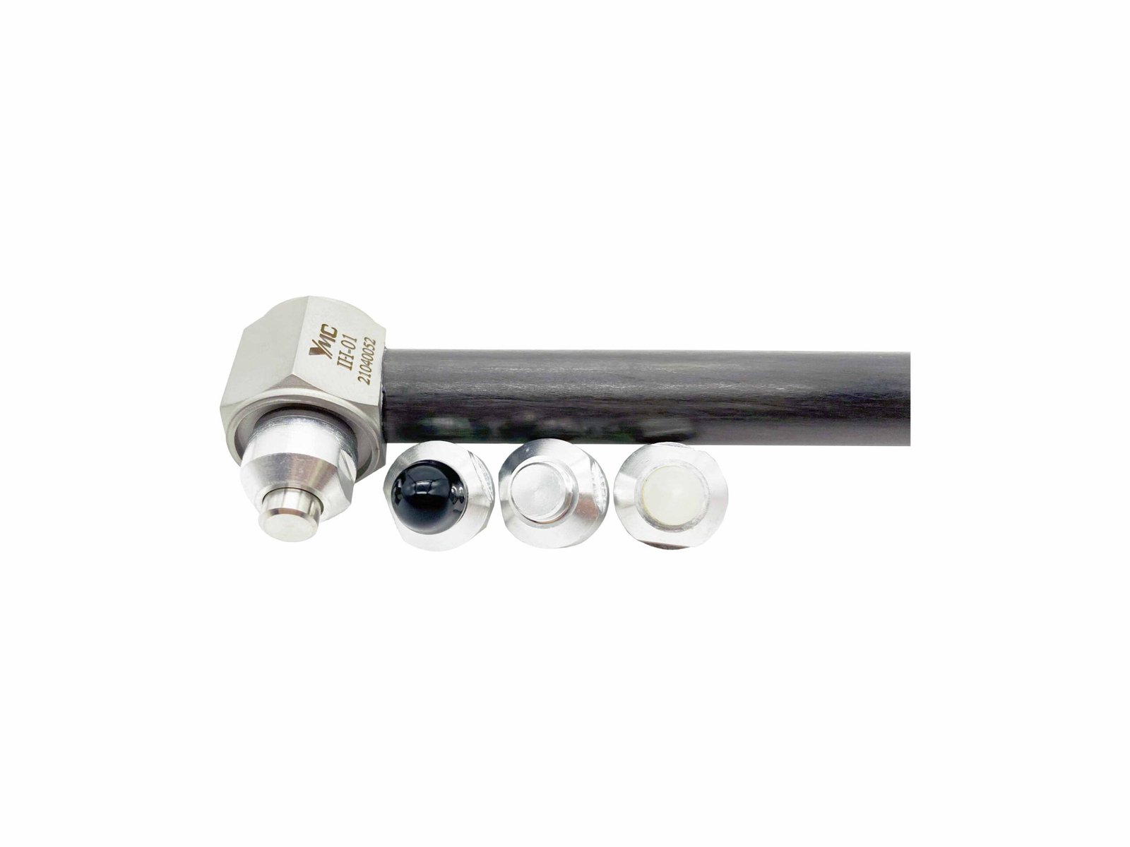 Impact Hammer-IH-01Rugged, force sensor into the hammer’s striking surface. Variety of hammers are suitable for different size test subjects. Tips offer frequency tailored impulse. Used for structure health testing, resonance determination, modal analysis.₹67,000View →
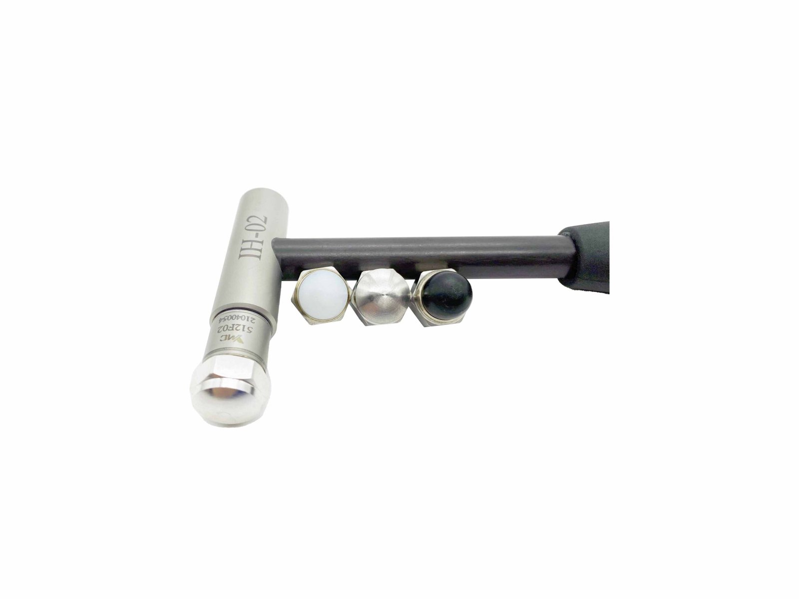 Impact Hammer-IH-02Rugged, force sensor into the hammer’s striking surface. Variety of hammers are suitable for different size test subjects. Tips offer frequency tailored impulse. Used for structure health testing, resonance determination, modal analysis.₹75,000View →
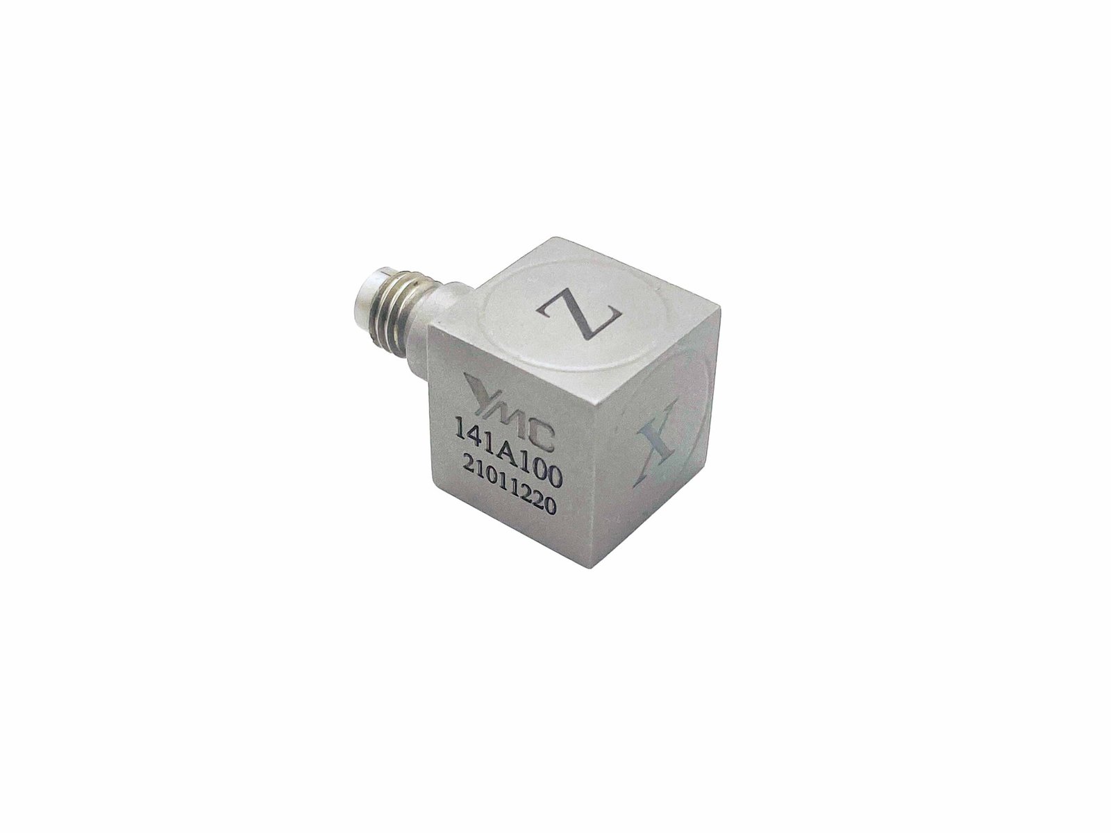 Miniature Tri-axial IEPE Accelerometer-141A100Small size and weight For circuit boards testing, small structural testing, drop testing, component testing and modal testing etc.₹1,21,145View →
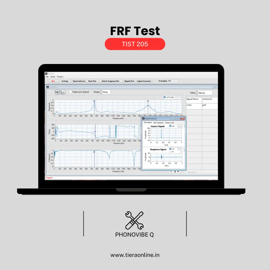 TIST 205 – FRF Test (Phonovibe Q)Use Cases Experimental Modal Analysis Product quality Natural Frequency Transmissibility,Vibration isolation Measurement₹41,472View →
Use cases
Where this shows up in the field
Plan the test, then run it once.
Most repeat modal tests are repeats because of a planning decision — a reference on a node, a boundary condition that did not match the model, or too few points to separate two shapes.
We supply the hammers, tri-axial sensors and simultaneous-sampling DAQ, and we will happily review a test plan before you instrument anything.
- IH-01 and IH-02 impact hammers with tip sets for bandwidth control
- Light tri-axial accelerometers to limit mass loading
- PhonoVibe Q/O/HD for simultaneous multi-reference acquisition
Where this sits on the TIERA learning ladder.
The theory behind this article is covered free, in full, by the TIERA 101 primers: Modal & Resonance 101, Measurement Setup 101. They are self-paced, interactive, and end in an exam and a certificate.
The primer covers resonance and mode shapes. Multi-reference planning, boundary-condition choice and MAC-based validation are Cat III/IV structural-dynamics material.
TIERA 101 is a free introductory primer, not an accredited ISO certification, and its hours do not count towards the formal training ISO 18436 requires.