Mode Shapes, Explained with a Skipping Rope
What a mode shape is, why one structure has several, when to reach for a hammer versus a shaker, and how to read an FRF — the short visual version for R&D teams chasing a ringing panel or bracket.
One rope, many modes
Swing a skipping rope slowly and it settles into one big arc. Swing it faster and it refuses to stay that way: it splits into two loops spinning in opposite senses, then three. Same rope, same tension — but each pattern only appears at its own particular speed, and each pattern has points that barely move at all while the rest of the rope flies.
That is modal behaviour in one sentence. A natural frequency is a rate of vibration the structure prefers; a mode shape is the pattern of motion it takes at that frequency. Every real structure — a bracket, an enclosure panel, a machine-tool spindle — behaves like many ropes at once, carrying a whole family of modes, each with its own frequency, its own shape, and its own still points.
Nodes, antinodes, and the sensor that sees nothing
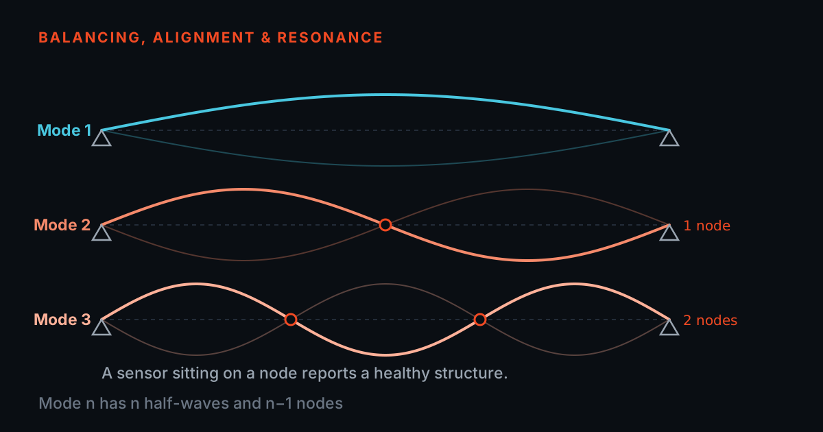
- A node is a real point on a real structure where a perfectly healthy sensor reports silence while the mode is ringing hard.
- The defence is several measurement points, not one — a roving hammer over a grid, or many response points captured at once with the phase between them intact.
- Phase means nothing on its own. State the reference degree of freedom and the sign convention next to the shape, or it is a picture rather than a measurement.
The still points are called nodes; the points of maximum swing are antinodes. Here is the classic beginner trap: glue an accelerometer onto a node of the mode you care about, and that mode simply vanishes from your measurement. The structure is ringing hard — your sensor happens to be sitting on the one spot that does not move. Mode 2 of a beam supported at both ends is the textbook offender, because its node sits exactly where intuition says to put the sensor: dead centre.
The defence is to measure at several points, not one — either by roving the hammer over a grid or by capturing many response points at once. This is where multi-channel capture earns its keep: a PhonoVibe O or HD records all inputs simultaneously on 24-bit converters, and that simultaneous sampling preserves the phase relationships between points — which, for mode shapes, are the data.
Phase means nothing on its own, so state the reference. The convention used throughout this post — and the usual one for a roving-hammer survey — is that phase is quoted relative to the fixed reference channel, the one degree of freedom that does not move between hits, and that a positive reading means motion along the positive sensor axis. On that convention a point reading 0° moves with the reference at the same instant, and one reading 180° moves against it. In the two-lobe shape above, every point in one lobe reads 0° and every point in the other reads 180°; the node is where the amplitude passes through zero and the phase flips. A shape animated without its reference degree of freedom and its sign convention written next to it is a picture, not a measurement.
Hammer or shaker?
An impact hammer is the fast way in. One calibrated tap injects energy at every frequency at once, so a handful of hits over a grid of points gives you the whole picture — ideal for quick surveys, small and mid-size structures, and roving-hammer or roving-response protocols. The PhonoVibe Eco X bench ships a 25 mV/N impact hammer and a 100 mV/g accelerometer in its starter pack, which is enough to run a complete FRF measurement in hammer mode on day one.
A shaker earns its place when you need controlled, repeatable, sustained energy: lightly damped modes that need dwell time to respond fully, coherence-critical averaging, or force levels a tap cannot deliver cleanly. The TWGM 206 waveform generator supplies the signals — pink and white noise, noise bursts, linear and log sine sweeps — and drives T-Xcite series shakers and amplifiers directly from the DAC output on PhonoVibe hardware, with a bandpass option that keeps excitation energy inside the band you are actually measuring. TIERA's shaker stands then hold the geometry: vertical, horizontal or oblique input, with wire-stinger arrangements for cleaner force paths into the structure.
Reading an FRF peak
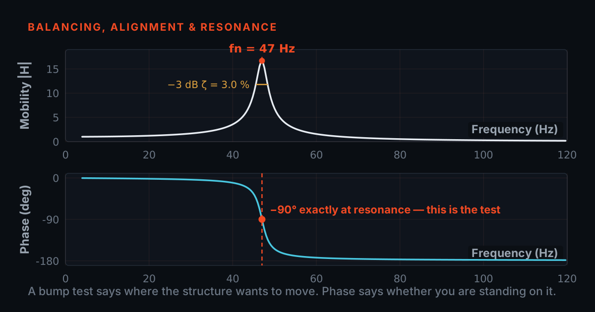
- A tall, narrow peak means light damping — the structure will ring long and loud if anything excites it there. A low, broad peak means damping is already soaking the energy up.
- An FRF has already divided response by the measured input force, which is what makes a mode shape a property of the structure rather than of whatever happened to be exciting it.
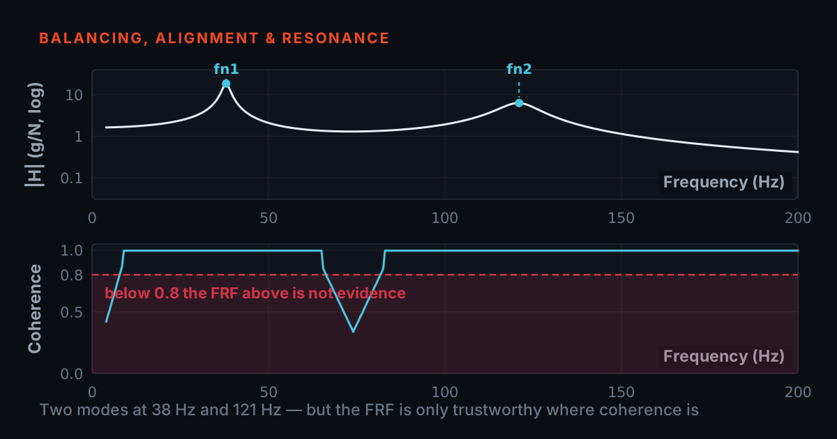
- Coherence is the quality gate: a measurement whose coherence falls below your acceptance threshold is telling you noise or a bad hit got into the data.
Whichever way you excite, the deliverable is a Frequency Response Function: how much the structure responds, per unit of input force, at every frequency. Each peak in the FRF is a natural frequency — one rung of the skipping-rope ladder. A tall, narrow peak means light damping: the structure will ring long and loud if anything excites it there. A low, broad peak means damping is already soaking energy up.
In the TIERA chain, TVIB's TFRT module takes the force and response channels captured on the TSAP201 base and computes the frequency-response function, flagging any measurement whose coherence falls below your acceptance threshold — your warning that noise or a bad hit has polluted the data. From there, FRFs export to your modal solver, or to the MODALVIEW add-on for ODS visualisation and experimental modal analysis when the structure is too complex to interpret by hand.
That word ODS needs its own paragraph, because treating it as a synonym for a mode shape is the single most common error in this subject and it changes what you are allowed to conclude. A mode shape is a property of the structure by itself: it is extracted from the FRF, where the response has already been divided by the measured input force, so it does not depend on what is exciting the structure or how hard. An operating deflection shape is what the structure is actually doing while the machine runs — the summed response to whatever real forces happen to be present, at one chosen frequency, with no force measurement anywhere in it. An ODS is therefore a superposition of however many modes are participating at that frequency, plus the forced response; a mode shape is one of the ingredients. They animate almost identically, which is exactly why they get confused.
The practical division of labour: an ODS tells you where a running machine is moving and by how much, which is what you want when a panel is buzzing on site and you cannot stop the plant to hit it with a hammer. A mode shape tells you what the structure would prefer to do if you excited it there, which is what you need before you decide to stiffen, add mass or damp — because those levers act on modes. If an ODS at the running speed happens to look like a mode shape, that is evidence the mode is being driven, not proof; the honest confirmation is an FRF measurement showing a resonance at that frequency. Whichever one is on the screen, the report should say which, and at what frequency.
From peak to fix: what the designer actually does
- Four levers: stiffen and the peak moves up, add mass and it moves down, damp and it stays put but gets shorter and broader, or move the excitation onto a node so the force can no longer feed the mode.
- The before-and-after FRF is the scoreboard — which is why the fixture has to stay identical between iterations, or the change you measure is the test setup.
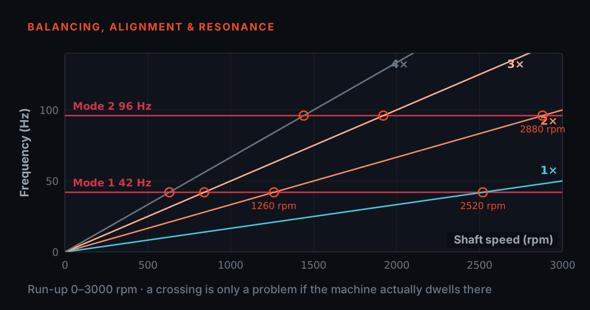
A ringing panel means an excitation frequency is sitting on, or near, a resonance peak. The designer has four levers. Stiffen the structure and the peak moves up in frequency — hopefully clear of the excitation band. Add mass and the peak moves down, which works in the other direction. Add damping — constrained-layer treatment, a tuned absorber — and the peak stays put but gets shorter and broader, so the ring dies quickly. Or move the excitation or mounting point onto a node of the offending mode, so the force can no longer feed it.
The FRF, measured before and after, is the scoreboard: it shows exactly which lever worked and by how much. This is also why teams test between design iterations on repeatable fixtures — a change in FRF should mean a change in the structure, not a change in the test setup.
A representative bench exercise — and where to learn more
A representative R&D exercise, not a specific customer: a sensor mounting bracket buzzes audibly on a running machine. The team bolts it to a bench fixture, marks a nine-point grid, and runs a roving-hammer test — impact hammer on the force channel, accelerometer on a response point, a PhonoVibe DAQ capturing both, TFRT computing the FRFs. The second peak lines up with the machine's excitation frequency, and the point-to-point phase shows a two-lobe shape whose antinode sits exactly at the sensor boss. A stiffening rib along that lobe moves the peak well above the excitation band; the repeat FRF confirms it, and the buzz is gone. Total instrument time is an afternoon — and notice the trap dodged: a single sensor placed at the bracket's centre node would have reported nothing wrong at all.
If you want the theory behind these pictures, the free primers at 101.tieraonline.in — start with Modal & Resonance 101 — walk through resonance, FRFs, and mode shapes at beginner pace; they are open primers, not accredited ISO certification. When you need formal, verifiable credentials for analysts, TIERA's TCAT programme (see /services) adds structured coursework with proctored examinations at exams.tieraonline.in.
TIERA instruments that do this work.

PhonoVibe Series — Sound & Vibration DAQ
Simultaneous sampling on every channel preserves the point-to-point phase that IS the mode shape; the Eco X bench adds a 20 N shaker plus hammer and accelerometer for a first modal grid.
- Channels
- 2 / 4 / 8 / 16 (D / Q / O / HD)
- ADC
- 24-bit, simultaneous sampling on every input
- PhonoVibe O / HD
- 128 kHz sampling · 0.5 Hz – 60 kHz · ±5 V input
- Eco X bench
- 4-ch DAQ + 20 N shaker, 150 W amplifier, 100 mV/g accelerometer + 25 mV/N impact hammer
- Sensor power
- IEPE / ICP / CCLD — 24 V, 4 mA, with TEDS recognition
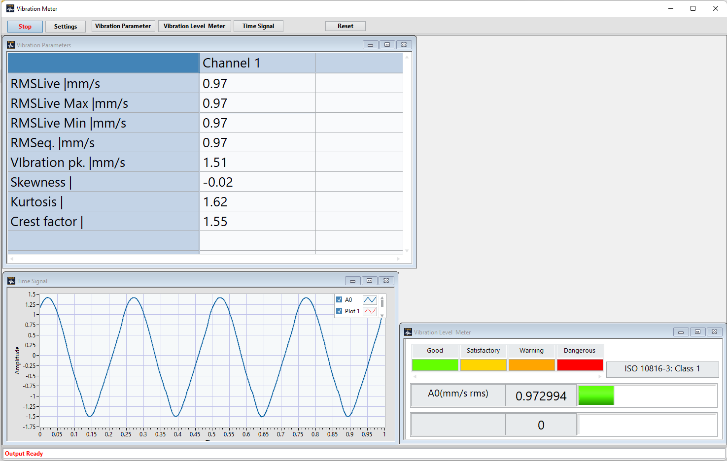
TWGM 206 — Waveform Generator
When the structure needs sustained, controlled energy instead of a tap — burst signals for coherent averaging and log sweeps that give lightly-damped modes time to respond.
- Signals
- Pink, white and random noise, noise burst, linear and log sine sweeps
- Noise output
- Bandpass filter limits energy to the measurement bandwidth
- Drives
- TIERA T-Xcite series electrodynamic shakers and amplifiers
- Integration
- Output via PhonoVibe DAC from within TVIB — one clock for excitation and response
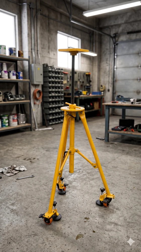
Vertical and Lateral Shaker Stands
Holds the shaker geometry — vertical, horizontal or oblique input through a wire stinger — so the force enters where you meant it to, run after run.
- Formats
- Vertical stand, lateral / horizontal excitation stand, mobile options
- Force input
- Wire-stinger and fixture arrangements for cleaner force input
- Intended for
- Modal, FRF, ODS and structural dynamics testing
- Compatibility
- Compact electrodynamic shakers and custom test fixtures
From the TIERA store
The kit for this job
What we would actually put in front of someone doing the measurement this post describes — not the whole catalogue.
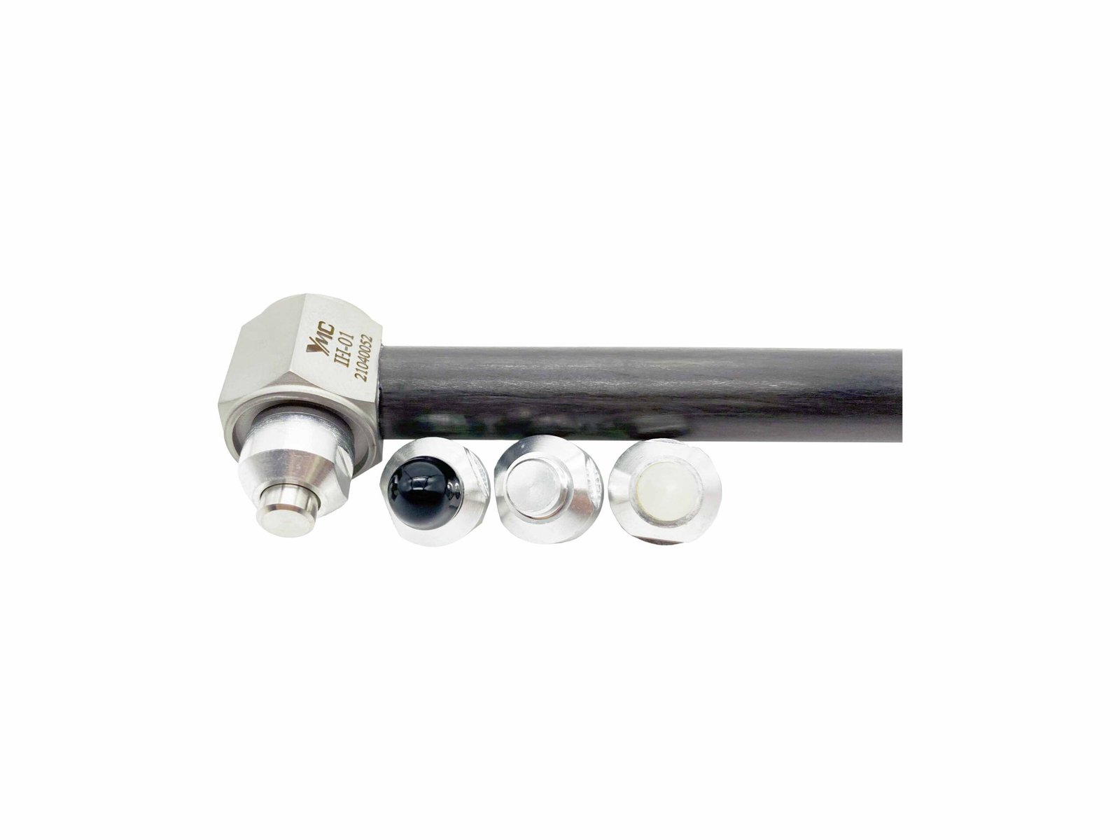 Impact Hammer-IH-01A rugged force sensor built into the hammer’s striking surface. A variety of hammers are suitable for different size test subjects. Tips offer a frequency-tailored impulse. Used for structure health testing, resonance determination, modal analysis.₹67,000View →
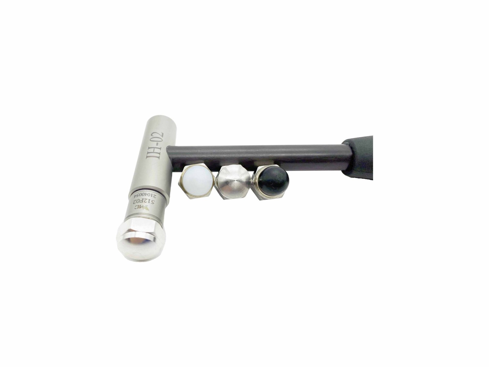 Impact Hammer-IH-02A rugged force sensor built into the hammer’s striking surface. A variety of hammers are suitable for different size test subjects. Tips offer a frequency-tailored impulse. Used for structure health testing, resonance determination, modal analysis.₹75,000View →
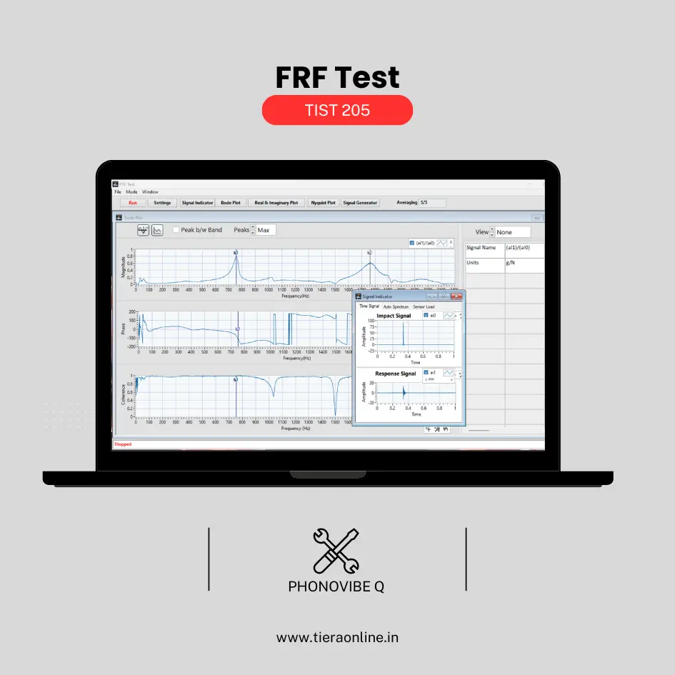 TIST 205 – FRF Test (Phonovibe Q)Use Cases Experimental Modal Analysis Product quality Natural Frequency Transmissibility,Vibration isolation Measurement₹41,472View →
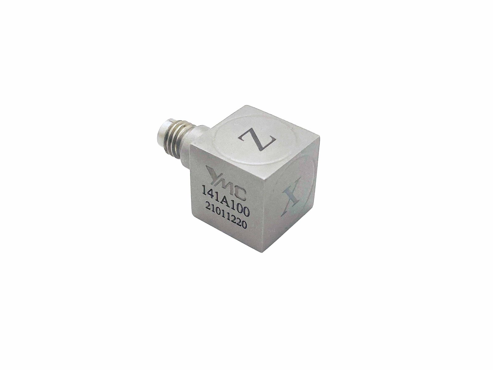 Miniature Tri-axial IEPE Accelerometer-141A100Small size and weight For circuit boards testing, small structural testing, drop testing, component testing and modal testing etc.₹1,21,145View →
Use cases
Where this shows up in the field
Everything between the tap and the mode shape, from one supplier
A modal test is a chain — excitation, transduction, simultaneous capture, FRF processing — and TIERA supplies every link. For hammer surveys, the PhonoVibe Eco X bench ships with a 25 mV/N impact hammer and a 100 mV/g accelerometer, enough to run your first full FRF grid on day one; for bigger structures and denser grids, PhonoVibe O and HD capture 8 or 16 channels on 24-bit converters with simultaneous sampling, so the phase between points — the mode-shape data itself — survives intact.
When the structure needs sustained, controlled energy instead of a tap, the TWGM 206 generator supplies noise, bursts and linear/log sine sweeps straight from the PhonoVibe's DAC into T-Xcite shakers and amplifiers, while TIERA's shaker stands hold the geometry — vertical, horizontal or oblique input through a wire stinger. TVIB's TFRT module computes the FRFs and flags low-coherence measurements before they pollute your data set; from there, export to your own modal solver or add MODALVIEW for ODS and experimental modal analysis.
- PhonoVibe O / HD — 8 or 16 channels, 24-bit ADCs, simultaneous sampling on every input to preserve inter-point phase for mode-shape extraction
- TWGM 206 waveform generator — pink/white noise, noise bursts, linear and log sine sweeps, with a bandpass option that keeps excitation energy inside your measurement band
- Vertical and lateral shaker stands — repeatable vertical, horizontal and oblique excitation with wire-stinger arrangements for clean force input
- TVIB TFRT + MODALVIEW — FRF measurement with coherence flagging, then ODS visualisation and experimental modal analysis, or export to the solver you already use
Where this sits on the TIERA learning ladder.
The theory behind this article is covered free, in full, by the TIERA 101 primers: Modal & Resonance 101. They are self-paced, interactive, and end in an exam and a certificate.
TCAT adds structured analyst coursework and proctored, exam-verified certification at exams.tieraonline.in — the free 101 primers cover the theory, TCAT proves you can apply it.
TIERA 101 is a free introductory primer, not an accredited ISO certification, and its hours do not count towards the formal training ISO 18436 requires.