


Shaker Testing: What the Stand Does, and Why a Good Shaker on a Bad Fixture Measures the Fixture
An electrodynamic shaker gives you controlled excitation — a known force, at a known frequency, repeatably. What decides whether the result means anything is the thing underneath it: the stand, the fixture and the boundary condition. Most disappointing shaker data is a fixture resonance wearing a costume.
Three quite different jobs, one machine
An electrodynamic shaker is a loudspeaker motor built to push a payload instead of air: a coil in a magnetic field, driven by an amplifier, producing a force proportional to current. That one mechanism gets used for three jobs that have almost nothing else in common, and confusing them is the source of a lot of wasted money.
Sensor calibration. A small shaker drives an accelerometer at a known acceleration — classically 1 g at 159.2 Hz — and you compare the sensor's output against a reference. The requirements here are precision and stability, not force. A calibration shaker that produces a beautifully pure, distortion-free 10 m/s² is worth far more than one that produces a filthy 100 m/s².
Modal excitation. A shaker drives a structure while you measure the force going in and the response coming out, giving you an FRF. Here you need controllable broadband excitation — random, burst random, or a swept sine — and above all a clean, measurable force input. This is where the attachment method matters more than the shaker.
Environmental and durability testing. Shake a product to a specified profile until it either survives or does not. This is the one that needs real force, real displacement and real duration, and it is a different class of machine from the first two.
A shaker sized for the third job is wasted on the first, and a shaker sized for the first cannot do the third at all. Decide which job you are buying for before you look at a single specification.
The stand is a spring, whether you meant it to be or not
Here is the failure that produces most of the bad data. You bolt a shaker to a stand, drive a structure, measure a beautiful FRF with a clear peak at 84 Hz — and that peak belongs to the stand.
A shaker pushing a structure gets pushed back, exactly as hard, in the opposite direction. That reaction force goes into whatever is holding the shaker. If the stand is flexible, it moves. If it moves, the shaker body moves, and the force actually delivered to your test article is no longer the force your amplifier commanded. Worse, the stand has its own natural frequencies, and near them the whole assembly behaves like a coupled two-mass system rather than a source driving a structure.
The tell is straightforward once you know to look: a peak that does not move when you change the test article, but does move when you change the setup. Add mass to your specimen and a genuine structural mode shifts down. A fixture resonance sits exactly where it was. That one check separates the two in about ninety seconds, and it should be routine.
The fixes are equally unglamorous: make the stand far stiffer and far heavier than the thing you are testing, keep the load path short and direct, and where possible arrange the reaction to go straight into a seismic mass or the floor rather than through a slender column.
Vertical or lateral is a boundary-condition decision
A vertical stand drives the payload along the gravity axis. Convenient for calibration — the sensor sits on the table and stays there — and it is the standard geometry for accelerometer verification. The catch is that the armature carries the static weight of the payload as well as the dynamic load, which eats stroke and can bias the suspension.
A lateral stand drives horizontally, which takes the payload weight off the armature entirely and puts it on a support. That matters when the payload is heavy, when you need the full stroke for the dynamics, or simply when the axis you must excite is horizontal.
The real point is that neither is better. The axis you excite has to be the axis your question is about, and the support has to impose the boundary condition your analysis assumes. If you are correlating against a free-free finite-element model and your specimen is bolted to a stand, the mismatch is not a small error — it is a different problem.
Stinger, and why you should not bolt the shaker to the structure
For modal work, the shaker is connected to the structure through a stinger — a slender rod, stiff along its axis and deliberately flexible in bending.
The reason is that you want to inject force along one axis and nothing else. Bolt a shaker rigidly to a structure and it will also apply bending moments and side loads as the structure moves, none of which your force transducer measures. Your measured FRF then relates a force you know to a response driven partly by forces you do not know, and the result is quietly wrong.
A stinger, being weak in bending, cannot transmit much moment — so the input really is close to the single axial force the force gauge is reading. Make it too long or too thin, though, and its own buckling and bending modes enter your frequency range. Short enough to stay stiff axially, thin enough to stay soft in bending, and always check that the stinger's own modes sit outside the band you care about.
How to size one without over-buying
Force rating is the headline number and the least useful one on its own. What you need is force at your lowest frequency of interest, because at low frequency the limit is not force at all — it is stroke. A 50 N shaker reaching 5 mm peak-to-peak cannot produce 1 g on a 2 kg payload at 5 Hz, no matter what its force rating says, because the displacement required exceeds what the armature has.
So: take your payload mass, take your required acceleration, take your lowest frequency. Compute the displacement that combination demands. Check it against stroke first, then check force against mass × acceleration, then confirm the armature resonance sits above your band. For calibration work, ignore force almost entirely and buy on distortion and stability instead.
TIERA instruments that do this work.
Vertical and Lateral Shaker Stands
The mass and stiffness under the shaker — the part that decides whether you measured your specimen or your fixture.
- Configurations
- Vertical and lateral
TXcite 50 Electrodynamic Shaker
50 N with amplifier — sized for modal excitation and sensor verification rather than durability testing.
- Force
- 50 N
- Supplied with
- Amplifier
T-Calibro Vibration Calibration System
When the job is sensor calibration, distortion and stability matter and raw force does not.
- Use
- Accelerometer and vibration sensor calibration
From the TIERA store
The kit for this job
What we would actually put in front of someone doing the measurement this post describes — not the whole catalogue.
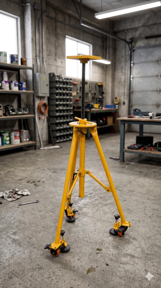 Vertical Shaker StandMechanical stand that positions an electrodynamic shaker for vertical excitation — safer handling, better alignment and repeatable force input for modal and structural dynamics testing.Request priceView →
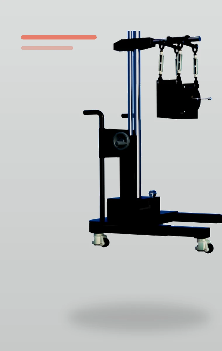 Horizontal / Lateral Shaker StandMechanical stand that adapts an electrodynamic shaker for horizontal and oblique excitation — safer handling, better alignment and repeatable force input for modal and structural dynamics testing.Request priceView →
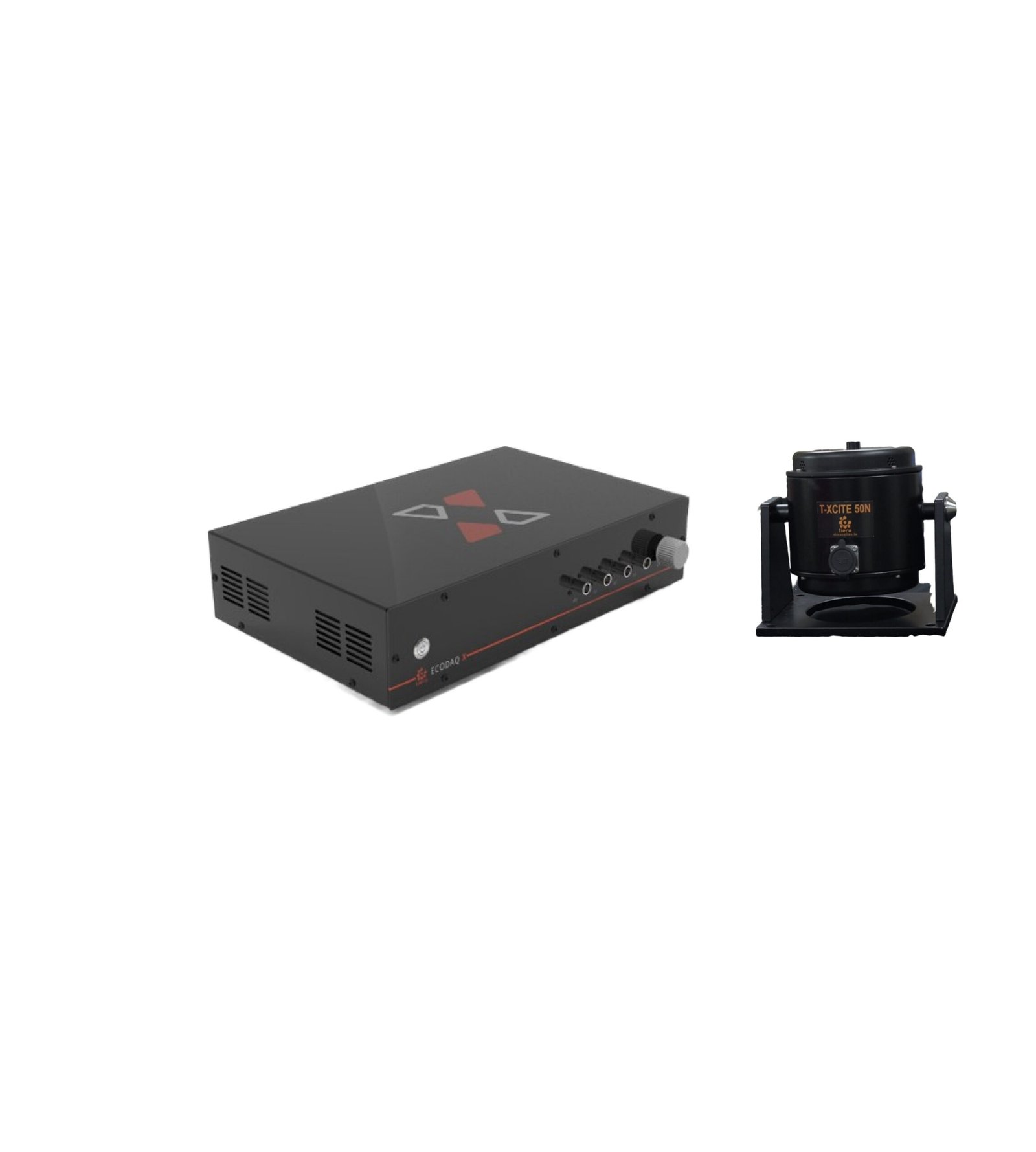 TXcite 50 – Electrodynamic Shaker (50 N) with AmplifierT-Xcite Permanent magnet modal shakers provide precise, reliable, stable and long-lasting operation. Highest quality materials, stringent quality control and rugged construction General mechanical mobility measurements Experimental modal analysis on most mechanical structures SISO, MISO. SIMO and MIMO modal test applications Advanced structural dynamics investigations Structural damage detection Finite element model correlation₹4,80,000View →
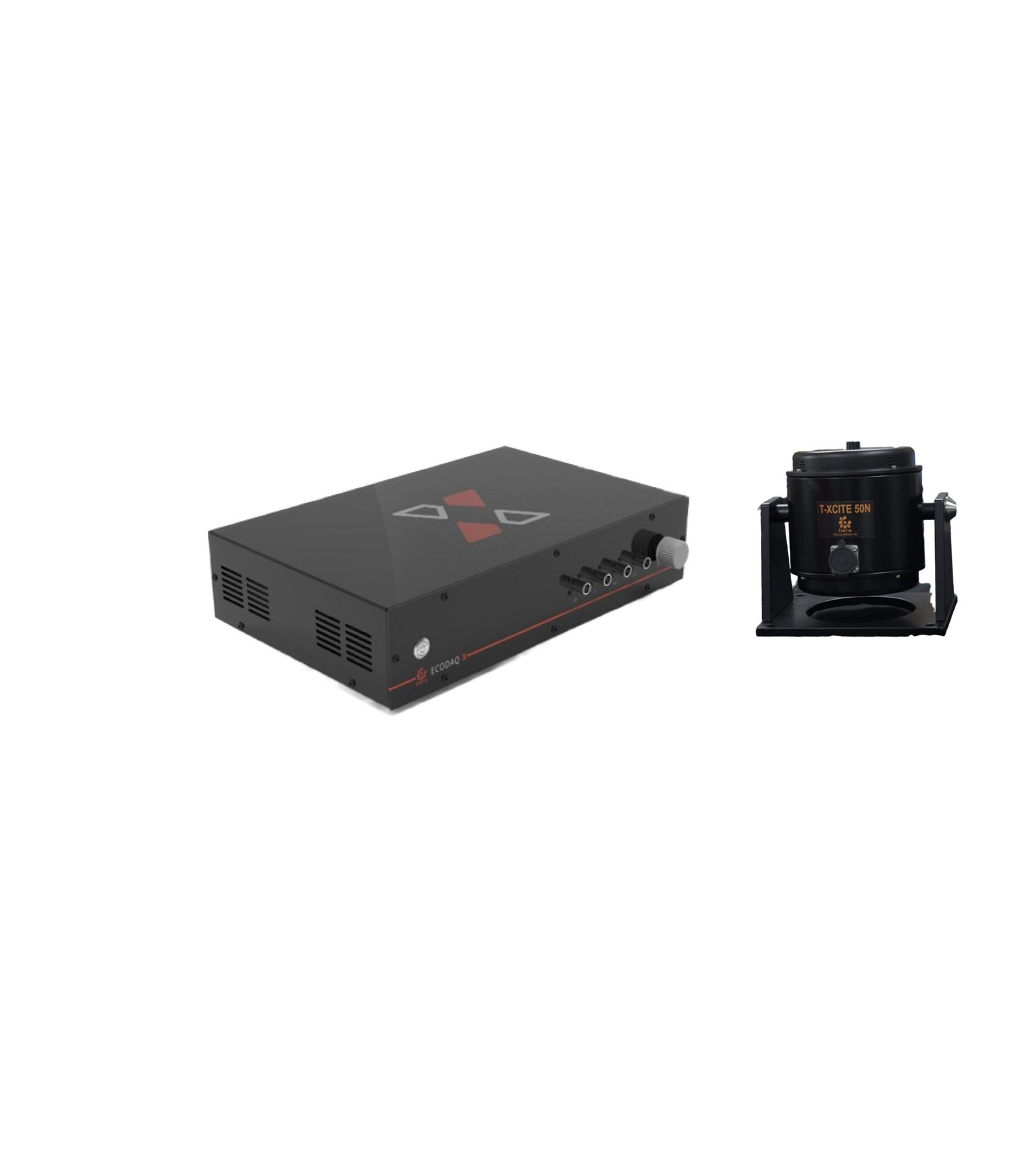 Vibration Shaker with AmplifierT-Xcite Permanent magnet modal shakers provide precise, reliable, stable and long-lasting operation. Highest quality materials, stringent quality control and rugged construction General mechanical mobility measurements Experimental modal analysis on most mechanical structures SISO, MISO. SIMO and MIMO modal test applications Advanced structural dynamics investigations Structural damage detection Finite element model correlation₹3,60,000View →
Use cases
Where this shows up in the field
Buy the stand with the same care as the shaker.
A shaker is a commodity in a way a fixture is not. The stand is where a test either becomes repeatable or becomes an argument, and it is the part most budgets under-spend.
Tell us the payload, the axis and the lowest frequency you care about, and we will size the pair together rather than selling you a force number.
- Vertical and lateral stands built for the reaction load, not just the mount pattern
- TXcite 50 with amplifier for modal and verification work
- T-Calibro when the job is calibration rather than excitation
Where this sits on the TIERA learning ladder.
The theory behind this article is covered free, in full, by the TIERA 101 primers: Modal & Resonance 101, Measurement Setup 101. They are self-paced, interactive, and end in an exam and a certificate.
The primer covers excitation and FRFs. Separating a fixture mode from a structural one, and choosing a boundary condition that matches the model you are correlating against, is Cat III/IV structural-dynamics work.
TIERA 101 is a free introductory primer, not an accredited ISO certification, and its hours do not count towards the formal training ISO 18436 requires.