Wired, Wireless, or a Walk: An Honest Decision Guide for Vibration Monitoring
Wireless vibration sensors are the fastest-growing way to instrument a plant — and the most oversold. This guide gives you the three questions that actually decide between a wired online system, a wireless sensor network, and a route with a portable analyser: the frequency you need, the cadence you need, and the cost per point. With a calculator you can drive, and a plain list of the jobs wireless cannot do.
Three ways to get a reading off a machine
Every vibration programme is one of three architectures, or a mix of them. A route: an analyst walks the plant with a portable analyser and a magnet, visiting each point on a schedule — high-quality data, human judgement on the spot, but only as often as someone walks. A wireless sensor network: battery-powered nodes bolted or magnet-mounted to each point, waking on a schedule, taking a short reading and radioing it to a gateway — cheap to install, dense coverage, but every reading is a snapshot. A wired online system: permanently cabled sensors into permanently powered acquisition — continuous, high-bandwidth, and the most expensive per point by a wide margin.
Vendors will happily sell you any of the three for any machine. The engineering question is which architecture matches each machine's failure physics and each point's economics — and the honest answer is usually a mix. CTC, whose Connect wireless line TIERA distributes in India, says as much in their own wired-versus-wireless whitepaper: they recommend hybrid deployments, and they state plainly that wireless MEMS sensors are best suited below 10 kHz, with wired sensors more appropriate where broad bandwidth or continuous monitoring is required. When the manufacturer of the wireless sensor tells you where not to use it, believe them.
This post turns that qualitative advice into three concrete gates — frequency, cadence, cost — and gives you a calculator for the third. If a machine fails all three gates for wireless, put it on copper or on a route. That is not a defeat for wireless; it is what makes the wireless part of your programme trustworthy.
What a wireless snapshot sensor actually is
Strip the marketing off and a wireless vibration node is a battery, a MEMS accelerometer, a small processor and a radio. Because the battery is finite, the node spends almost all of its life asleep. On CTC's Connect line — the family TIERA supplies — the entry sensor takes a 500 ms triaxial reading on a factory-set interval between one and twenty-four hours and transmits three numbers per axis: Peak, RMS and Peak-to-Peak. The dynamic sensors in the family capture an actual waveform on a user-set schedule, or on demand from the gateway. CTC states battery life of one to four years — and the fine print matters: their battery-life charts assume two readings per day, and CTC's own datasheet says to replace the battery at half the usual interval above 50 °C, an ambient that a sensor on a pump casing in an Indian May will meet.
Everything a wireless node can and cannot do follows from that duty cycle. Between readings, the machine is unobserved. A transient event — a rub on startup, a surge, a load swing — that happens between snapshots simply does not exist in the data. That is not a defect; it is the design trade that buys years of battery life. But it has a hard consequence that TIERA states as its own engineering judgement, because it decides safety-critical purchases: a snapshot sensor is condition monitoring, not machine protection. A machine that can destroy itself in seconds — a turbine losing a blade, a compressor surging — needs a continuously wired protection system with hardwired trip logic. No sensor that sleeps between readings, from any vendor, is a substitute for that, and a vendor who implies otherwise is selling you a liability.
The radio architecture matters too, mostly for what it does not require. CTC's Connect sensors talk Bluetooth Low Energy 5.2 to an ACCESS360 gateway on your LAN; the gateway serves its own browser-based software locally and exposes MQTT and WebSocket interfaces for your own systems. There is no cloud dependency and no recurring subscription — CTC's stated architecture keeps the data on your network. For Indian plants with intermittent WAN connectivity, or IT policies that forbid OT data leaving site, that is a genuinely useful property, not a footnote.
Gate one: the frequency your fault lives at
The first gate is physics, and it is pass/fail. Every fault you want to catch has a characteristic frequency, and the sensor must measure well above it. Unbalance and misalignment live at one and two times running speed — 25 to 100 Hz on typical Indian 1,500/3,000 RPM machines. Bearing defect rates sit at a few hundred hertz, but the early evidence — the ringing that envelope analysis demodulates, explained in /blog/bearing-envelope-explained — lives in the structural resonance region of one to several kilohertz, and you want harmonics of gear mesh, which for a 3,000 RPM pinion with 23 teeth is 1,150 Hz at the fundamental and 3.45 kHz at the third harmonic. All of this is reachable by a good wireless sensor.
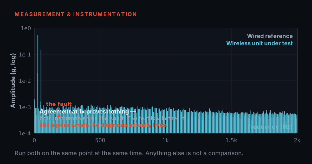
What is not reachable: CTC's own whitepaper states that wireless sensors are typically MEMS-based and best suited to monitoring below 10 kHz, and recommends wired sensors for high-speed machinery and broad-bandwidth analysis. Concretely, on CTC's entry overall sensor the factory-configured measurement bands top out at 5 kHz. So a high-speed gearbox whose mesh harmonics run past 10 kHz, an ultrasonic-range lubrication programme, or any analysis leaning on very-high-frequency content belongs on a wired IEPE accelerometer — see /blog/choosing-an-accelerometer-for-bearing-enveloping for how to pick one. The low end has a gate too: very slow machinery — slew bearings, kiln support rollers turning at a few RPM — produces defect energy at fractions of a hertz, below the low-frequency cutoff of general-purpose MEMS bands, and needs specialist low-frequency instrumentation and patience, not a snapshot node.
The rule: write down the highest frequency your diagnosis needs — not the highest the machine produces — and the lowest. If the highest exceeds roughly 10 kHz (CTC's own line for MEMS wireless), or the lowest sits below a few hertz, that point fails the wireless gate regardless of how attractive the installation economics look.
Gate two: the cadence your failure mode needs
The second gate is time. Faults develop over a characteristic interval — the P-F interval, the time between when a fault becomes detectable and when it becomes a functional failure. Rolling-element bearing damage in a normally loaded pump develops over weeks to months. For that physics, a good reading twice a day is genuinely excellent surveillance — better than a monthly route by a factor of sixty in cadence — and twice a day is exactly the basis CTC quotes its battery life on. This is the sweet spot where wireless is not a compromise but an upgrade.
Now run the same logic in reverse. A monthly route gives you twelve looks a year; it suits slow-developing faults on machines where a missed month is survivable — which is most balance-of-plant machinery, and is why routes have worked for forty years. A wireless network at one to twenty-four readings per day suits everything the route suits, plus faults that develop over days, plus machines that are unsafe or awkward to reach with a magnet while running. What neither can do is catch what develops in minutes. If the credible failure mode on a machine can go from detectable to destructive inside one reading interval, no snapshot cadence is honest surveillance — that machine needs wired continuous monitoring, and if it is critical enough, hardwired protection. That framing is TIERA's, but it follows arithmetically from any snapshot architecture's duty cycle.
A practical corollary for the wireless case: pick the reading interval from the failure physics, not from enthusiasm. Every extra reading spends battery — remember the two-readings-per-day basis under CTC's battery charts. Four readings a day on a general-purpose pump buys you nothing diagnostically over two, and shortens the maintenance interval of the one consumable in the system.
Gate three: the cost per point — run your own numbers
The third gate is money, and this is where the argument usually gets dishonest — because every vendor's example plant is shaped to flatter their architecture. So instead of our example, here is the arithmetic with your numbers. The calculator below compares the five-year cost of the three architectures for one plant. Every price in it is an illustrative default that you should overwrite with your own quotes — none of them is a CTC or TIERA price. The structural facts it encodes are real, though: wired cost scales with cable metres as much as with channels; wireless cost is dominated by sensor count with a small gateway term (CTC's gateway handles twenty concurrent sensor connections and load-balances across multiple gateways, so gateways are rarely the binding cost); route cost is dominated by recurring analyst-days, which is why it looks cheap in year one and is not by year five.
Two physics flags ride on top of the money, because a cheap architecture that cannot see your fault is not cheap. If you push the required frequency above 10 kHz the calculator flags wireless as unsuitable, quoting CTC's own guidance. If you tick continuous protection, it flags both wireless and route, on TIERA's judgement stated above.
Every price below is an illustrative editable default, not a CTC or TIERA price — overwrite with your own quotes. Five-year horizon. Wired and wireless assume permanent coverage of every point; the route assumes the same points walked on a schedule.
⚠ Above 10 kHz: CTC's own whitepaper says wireless MEMS sensors are best suited under 10 kHz — use a wired sensor for this point.
⚠ Protection needs continuous wired monitoring with trip logic. Neither snapshot wireless nor a route qualifies — TIERA's judgement, and non-negotiable.
When wireless is the wrong answer
A distributor who never says this is not advising you, so here is TIERA's plain list, with CTC's own positions cited where they exist. Machinery needing continuous protection: snapshot cadence disqualifies it, as argued above. Analysis above 10 kHz: CTC's whitepaper assigns this to wired sensors, and we agree. Severely EMI-dense areas and regulated environments: CTC's whitepaper itself prefers wired here — think VFD-crowded MCC rooms and pharmaceutical or oil-and-gas compliance regimes. Hazardous (classified) areas: we have found no published hazardous-area certification for the Connect wireless line, so treat it as unrated for classified areas unless CTC confirms a rating in writing for the exact part number you intend to install — never infer one. Very slow machinery: sub-hertz defect energy sits below general-purpose MEMS measurement bands. Machines where an overall number cannot decide anything: an overall-only node on a machine you would only strip down on diagnostic evidence gives you an alarm you cannot act on — the subject of the companion post at /blog/overall-vs-dynamic-wireless-sensors.
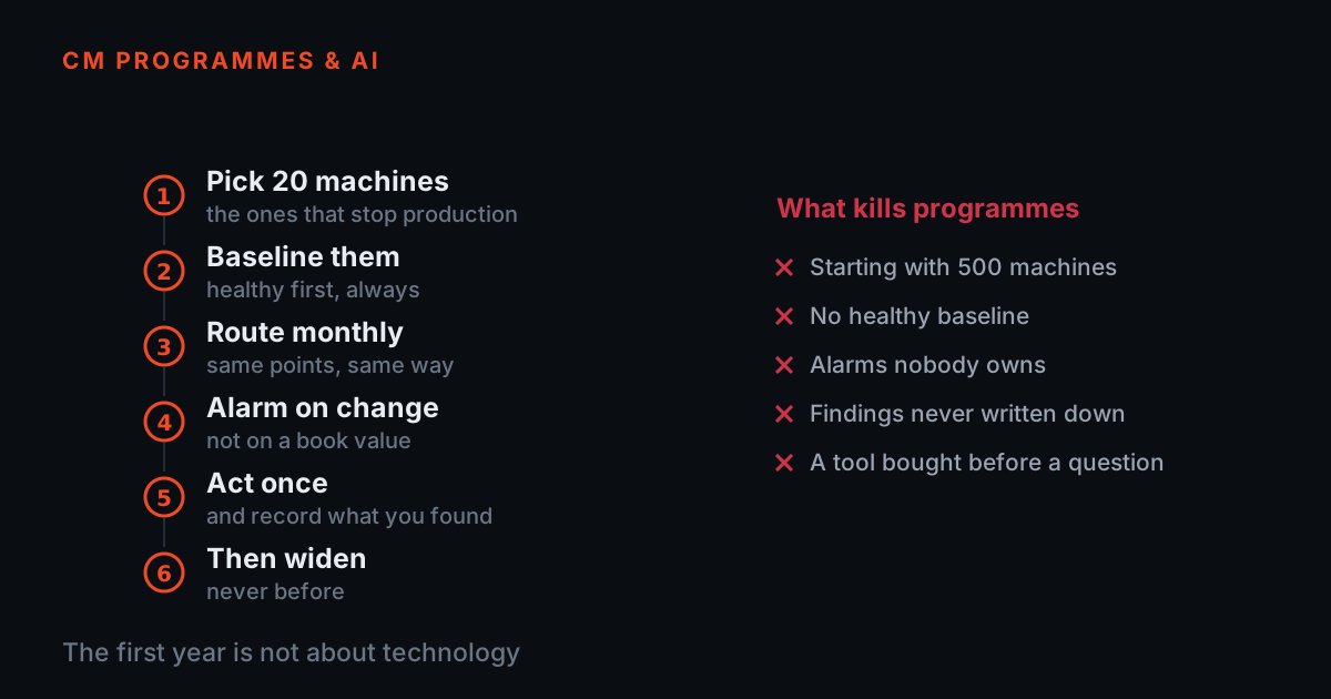
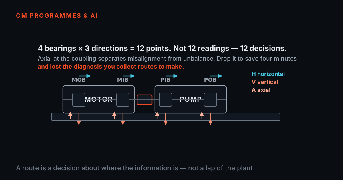
None of these kill the technology; they scope it. In a typical Indian process plant the honest allocation looks like: a handful of critical machines on wired online monitoring (and protection where warranted), the broad middle of the fleet on wireless — dynamic-waveform nodes on machines whose teardown decisions need evidence, overall nodes on the rest — and a periodic expert route over the top, because a portable analyser in trained hands remains the best diagnostic instrument on site. That is also, incidentally, the hybrid deployment CTC's own whitepaper recommends. The route design itself is covered in /blog/route-design-and-measurement-points, and the programme economics in /blog/starting-a-cm-programme.
India-specific fine print
Three local realities deserve a paragraph each before you sign a purchase order. Heat. CTC rates the Connect sensors to 80 °C operating, which covers most casing temperatures — but the battery rule above 50 °C ambient is the one that bites budgets: across much of India that is not an exceptional condition but April to June. Plan battery changes at the two-year mark for outdoor and rooftop installations and treat four years as a coastal-winter best case; the calculator above does this automatically.
Water and dust. CTC specifies IP67 ingress protection for the entry wireless sensor — genuinely monsoon-appropriate — and the gateway is specified for −20 to 70 °C. Note the gateway uplinks over Ethernet with PoE, not Wi-Fi: an old switchroom without PoE switches needs a PoE injector in the plan, a small line item that derails commissioning day when forgotten.
Logistics. The sensors run on lithium thionyl chloride primary cells, which travel under dangerous-goods provisions (UN3091 fitted, UN3090 spares) — order spare batteries with the sensors rather than as an emergency air shipment later, and remember CTC requires the battery removed before any RMA return. And a fact CTC has no reason to address but an Indian buyer must: the radio is 2.4 GHz Bluetooth Low Energy, the de-licensed band — but confirm the current WPC/ETA import-approval status for the specific radio module with your supplier (TIERA handles this for units we import) before a container sits in customs teaching you the rules.
TIERA instruments that do this work.
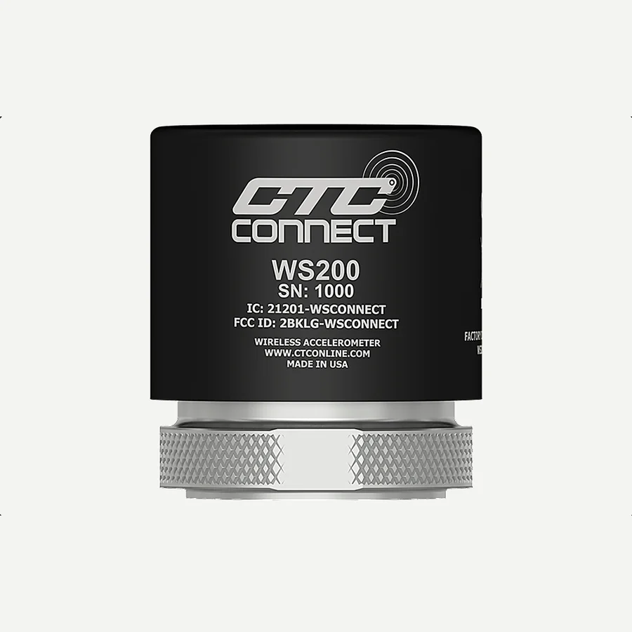
CTC WS200 Series ConnectSens Wireless Sensor
The dynamic-waveform wireless node for the middle of the fleet — actual time waveforms on a schedule or on demand, not just an overall number.
- Type
- Single-axis dynamic vibration + temperature
- Radio
- Bluetooth Low Energy 5.2, 1,200 ft (366 m) line-of-sight
- Battery
- User-replaceable, up to 4 years (CTC, at 2 readings/day)
- Configuration
- User-programmable via ConnectView; on-demand readings
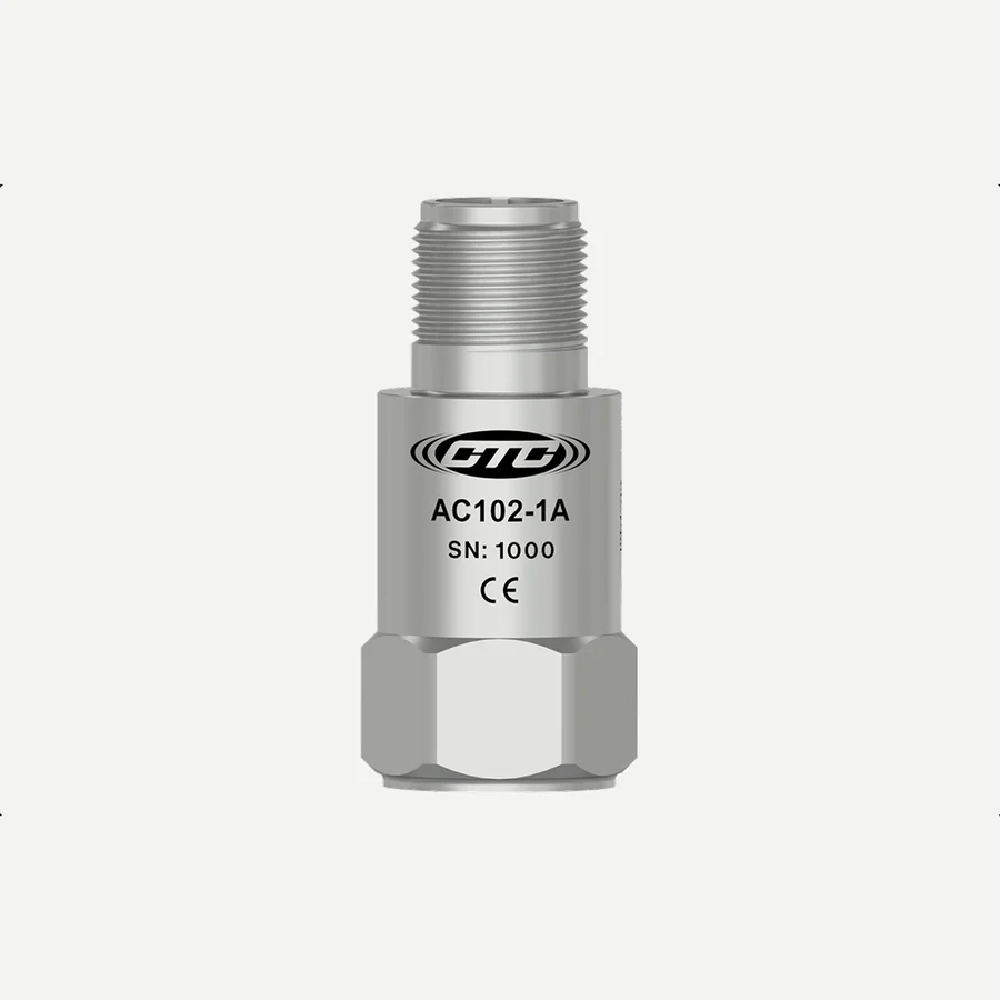
CTC 100 mV/g Standard Size Accelerometers
The wired half of the hybrid: for points that fail the 10 kHz gate, EMI-dense areas, and anywhere a cable is cheaper than a battery habit.
- Sensitivity
- 100 mV/g
- Dynamic range
- ±80 g
- Family
- AC102 / AC104 / AC150 and variants

PhonoVibe Q — 4-Channel IEPE DAQ
The route and verification instrument: when a wireless node raises its hand, this is what confirms the diagnosis before money is spent on a teardown.
- Channels
- 4, simultaneous, 24-bit
- Bandwidth
- 0.5 Hz – 60 kHz at 128 kHz sampling
- Sensor power
- 24 V, 4 mA IEPE built in
From the TIERA store
The kit for this job
What we would actually put in front of someone doing the measurement this post describes — not the whole catalogue.
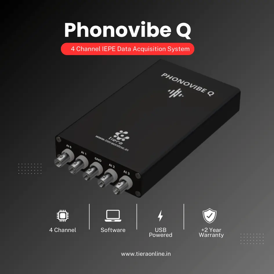 4 Channel IEPE Data Acquisition System – Phonovibe QFour Channels Standard plug & play USB Powered Take data from accelerometers, microphones, hammers, or any other IEPE Sensors T- VIB Software to acquire time waveforms, frequency spectra, overall vibration levels, FRF’s and octave measurements ** Windows 10 or above Operating System ** T-VIB Software base version comes with Time and Spectrum with Post processor TSAP 201. Check out TVIB Software regarding more module options.₹2,88,000View →
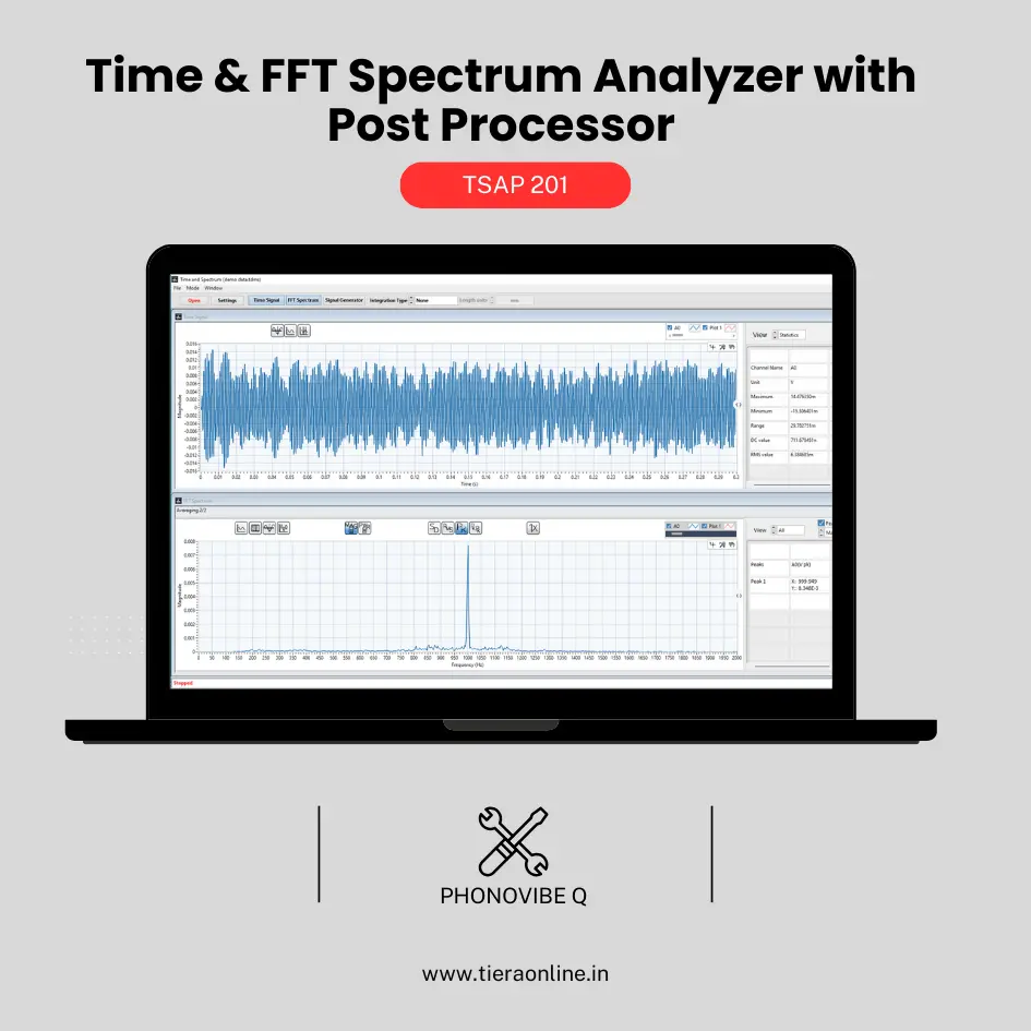 TSAP 201 -Time & FFT Spectrum Analyzer with Post Processor (Phonovibe Q)Use Cases Bump Test Product Development Off route Machine Vibration analysis. Drop Test Product Development & Research₹34,560View →
Use cases
Where this shows up in the field
One supplier for all three architectures — and honest advice about which one your machine needs
TIERA is the authorised Indian distributor for CTC (Connection Technology Center, USA) — the Connect wireless line and the wired accelerometer families alike — and builds the PhonoVibe portable analysis chain in-house. That mix is the point: because we sell all three architectures, we have no reason to force your plant into one of them. Send us your machine list with speeds, criticalities and distances, and we will come back with a split — wired, wireless, route — you can defend to your management and your auditors.
Detailed specifications for the WS200 and WS300 dynamic wireless sensors, and pilot-kit pricing for the Connect line, are available on request.
- CTC Connect wireless — overall and dynamic-waveform sensors, gateway, LAN-only software, no subscriptions
- CTC wired accelerometer families for the points wireless cannot serve
- PhonoVibe + TVIB for the expert route and diagnostic verification
- A written wired/wireless/route allocation for your machine list, with the reasoning shown
Where this sits on the TIERA learning ladder.
The theory behind this article is covered free, in full, by the TIERA 101 primers: Vibration 101 (Foundations), Measurement Setup 101. They are self-paced, interactive, and end in an exam and a certificate.
The free 101 primers cover the measurement basics behind these decision gates; TCAT Cat II adds the programme-design discipline — matching architecture to failure mode and defending the allocation — that this post can only sketch.
TIERA 101 is a free introductory primer, not an accredited ISO certification, and its hours do not count towards the formal training ISO 18436 requires.