


Validating a Wireless Vibration Sensor: What to Measure Before You Ship It
A wireless sensor has failure modes a wired one does not: a duty cycle, a battery, an internal clock and a radio between the measurement and the answer. Amplitude accuracy on a calibration shaker proves none of them. Here is the validation set that actually predicts field behaviour.
The reference chain comes first
Every claim you make about your sensor is a comparison against something else, so the something else has to be beyond argument. A validation lab needs a traceable reference accelerometer, a calibration exciter capable of a clean, low-distortion output, and a wired reference acquisition path whose own uncertainty is small compared with the tolerance you are validating against.
Write the uncertainty budget down before you start. If your reference chain carries ±2% and you are validating a ±5% amplitude claim, you have very little margin and you need to say so. Teams routinely validate a tight specification with a loose reference and then defend the result in the field, which is an uncomfortable position to be in.
Everything below assumes the wireless unit and the reference are measuring the same motion at the same place — which in practice means a mounting fixture that holds both without introducing a resonance of its own inside your band. That fixture is part of the reference chain and deserves the same scrutiny.
The tests a wired sensor also needs
Amplitude accuracy across the band. Not one point at 159.2 Hz. Sweep the frequency range you claim and record the deviation at each point; the interesting behaviour is always at the ends. Repeat at several amplitude levels, because linearity failures show up at the extremes and nowhere else.
Transverse sensitivity. Drive perpendicular to the sensitive axis and measure what leaks through. On a triaxial unit this matters twice over: cross-axis leakage corrupts the axis you were not driving and quietly inflates a vector sum.
Resonance and usable bandwidth. Find the mounted resonance and state the usable band honestly relative to it. A specification quoting a flat response up to a frequency uncomfortably close to the resonance is a specification that will not survive a customer's own check.
Temperature. Sensitivity drifts with temperature and the drift is rarely linear. If the unit will sit on a pump casing in an Indian summer, validate at that temperature, not at 23 °C.
Noise floor. The lowest signal the sensor can actually resolve sets whether it can see an incipient fault at all. Measure it, do not compute it from a datasheet component.
The tests that only apply because it is wireless
Duty cycle and what it hides. Most wireless sensors do not measure continuously — they wake, sample for a few seconds, compute, transmit, and sleep. Everything that happens while asleep is invisible. Validate what the sensor reports when the event is shorter than the sleep interval: an intermittent rub, a load transient, a startup. A unit that reports a clean trend through an event it never sampled is not wrong about its samples; it is wrong about the machine, which is what the customer cares about.
Clock accuracy and drift. The internal oscillator sets the actual sample rate. If it is off by 0.5%, every frequency the sensor reports is off by 0.5%, and a bearing fault frequency computed from it lands in the wrong place. Worse, oscillator drift is temperature-dependent, so a unit that is accurate on the bench moves in the field. Validate the sample rate directly, against a known frequency, at temperature.
Timestamp integrity across a fleet. If two sensors on the same machine disagree about when a sample was taken, you cannot compare phase between them and you cannot correlate an event across the train. Any claim about multi-point analysis depends on synchronisation you have measured, not on a protocol's promise.
Battery behaviour at the end of life. The important question is not how long it lasts — it is what it does as it dies. Does sensitivity drift as the supply sags? Does the radio start dropping packets before the sensor stops reporting? A unit that degrades silently is far more dangerous than one that stops.
Packet loss and what fills the gap. Radios drop data. Find out what the receiving system does with the hole: interpolate, repeat the last value, or mark it missing. A gap filled by interpolation and then trended looks like a healthy machine.
On-board processing. If the unit computes RMS or a spectrum internally and transmits only the result, then you are validating an algorithm as well as a sensor. Feed it a known signal and check the computed value against the same computation on the reference waveform — window, averaging and scaling conventions differ between implementations far more often than anyone expects.
Use a fault simulator, not just a shaker
A calibration exciter drives a single clean frequency. It tells you the sensor is accurate. It cannot tell you whether the sensor is useful, because no machine produces a single clean frequency.
Put the unit on a machine with real faults instead, alongside a wired reference, and ask the questions a customer will ask. Does the wireless unit resolve a bearing race comb, or has its on-board processing smoothed it away? Does it see a half-order component that indicates looseness? At what defect severity does it first report a change, compared with the wired chain — and is that gap acceptable for the application you are selling into?
This is where a fault simulator earns its place in a sensor validation lab. It produces a known fault, at a chosen severity, repeatably, so you can characterise detection threshold rather than merely amplitude accuracy — and you can hand a customer a curve instead of an adjective.
Report it in a form a customer can check
State the reference chain and its uncertainty. Give amplitude deviation as a curve across the band, not a single worst-case number. State the usable bandwidth relative to the mounted resonance, and say what mounting it assumes — because a magnet-mounted unit and a stud-mounted unit are different instruments above a few kHz.
Report the duty cycle explicitly and say plainly what class of event it can miss. Give the measured sample-rate accuracy and its temperature dependence. Say what happens on packet loss.
A validation report that says all of this is longer and less flattering than one that quotes ±3% at 159.2 Hz. It is also the one that survives the customer's own lab, and that is the only test that eventually matters.
TIERA instruments that do this work.
T-Calibro Vibration Calibration System
The traceable reference chain every claim in your datasheet ultimately rests on.
- Use
- Accelerometer and vibration sensor calibration

TMFSS — Machinery Fault Signature Simulator
Characterise detection threshold against known faults at chosen severities — what a shaker cannot tell you.
- Fault library
- 30+ faults in the base kit
PhonoVibe Q — 4-Channel IEPE DAQ
The wired reference path running alongside the unit under test, sampling simultaneously.
- Channels
- 4
From the TIERA store
The kit for this job
What we would actually put in front of someone doing the measurement this post describes — not the whole catalogue.
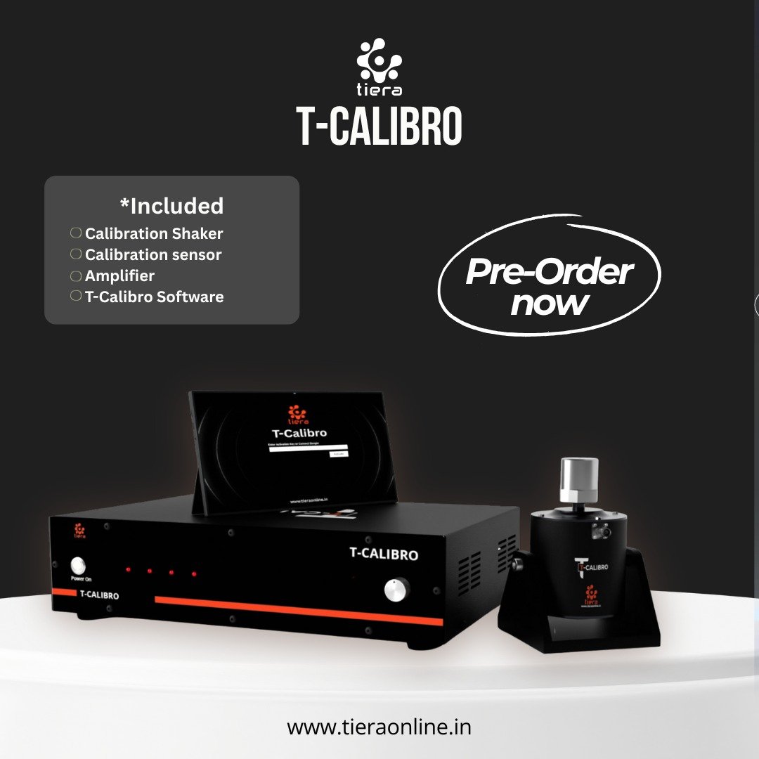 T-Calibro _ Precision Sensor Calibration Device for Accelerometers & Vibration SensorsT-Calibro is a high-performance PC-based vibration calibrator designed to calibrate and verify the working conditions of accelerometers, velocity sensors, and vibration meters. It provides stable, traceable vibration signals and supports both IEPE, charge, and voltage-type sensors, ensuring complete flexibility for industrial, laboratory, and R&D environments.₹18,00,000View →
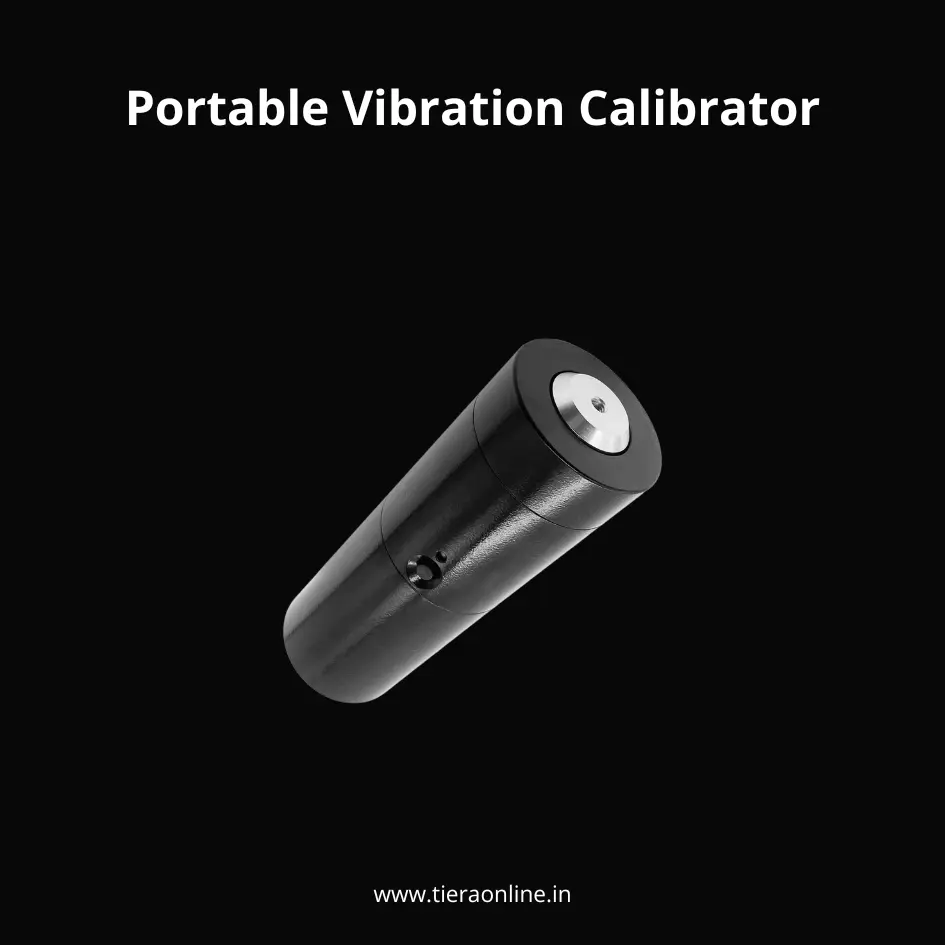 VC 01- Portable Vibration CalibratorVibration Calibrator Rapid judgement measurement system integrity. Rapid measurement of the Sensitivity of the Acceleration/ Velocity/Displacement sensors. Battery powered with automatic shutdown. Self-contained vibration reference. Small size. Light weight₹1,41,000View →
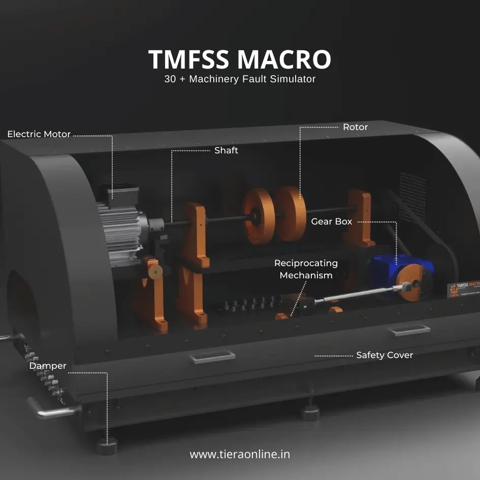 Machinery Fault Signature SimulatorTiera’s Machine Fault Simulator (TMFSS) is a valuable tool for industries and researchers, simulating over 30 real-world faults such as: Bearing faults: outer race defects, inner race defects, cage defects. Motor faults: stator faults, rotor faults, electrical unbalance. Gearbox faults: gear wear, misalignment, gear tooth damage. Etc..₹13,53,600View →
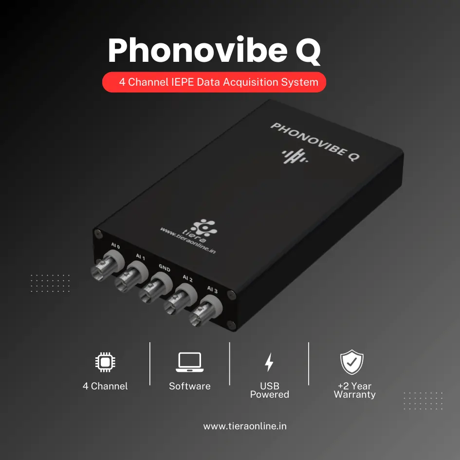 4 Channel IEPE Data Acquisition System – Phonovibe QFour Channels Standard plug & play USB Powered Take data from accelerometers, microphones, hammers, or any other IEPE Sensors T- VIB Software to acquire time waveforms, frequency spectra, overall vibration levels, FRF’s and octave measurements ** Windows 10 or above Operating System ** T-VIB Software base version comes with Time and Spectrum with Post processor TSAP 201. Check out TVIB Software regarding more module options.₹2,88,000View →
Use cases
Where this shows up in the field
Validate against a machine, not only against a shaker.
Sensor OEMs come to us for the wired reference half of the lab: a traceable calibrator, a simultaneous-sampling DAQ, and a fault rig that makes detection threshold a measured curve rather than a claim.
If you are preparing a datasheet you expect customers to test, that combination is what makes it hold up.
- T-Calibro and portable calibrators for the traceable reference
- TMFSS for repeatable, severity-graded known faults
- PhonoVibe for the simultaneous wired reference channel
Where this sits on the TIERA learning ladder.
The theory behind this article is covered free, in full, by the TIERA 101 primers: Accelerometer & DAQ Selection 101, Measurement Setup 101. They are self-paced, interactive, and end in an exam and a certificate.
The primer covers sensors and calibration. Designing a validation programme that predicts field behaviour — duty cycle, clock drift, detection threshold — is applied Cat II/III work.
TIERA 101 is a free introductory primer, not an accredited ISO certification, and its hours do not count towards the formal training ISO 18436 requires.