


Measuring Sound Absorption in an Impedance Tube — and Why Your Number Disagrees With the Datasheet
The two-microphone transfer-function method (ISO 10534-2) measures a material's normal-incidence absorption coefficient in a tube the size of a drainpipe. It is fast, repeatable and cheap — and it answers a narrower question than most people think, which is exactly why lab numbers and reverberation-room numbers disagree.
What the tube is actually doing
Put a sample of material at one end of a rigid tube and a loudspeaker at the other. Drive the speaker with broadband noise. The sound travels down the tube, hits the sample, and part of it comes back. Incident wave going one way, reflected wave coming the other, superimposed in the same tube.
If you can separate those two waves, you know exactly how much energy the material absorbed. That is the whole measurement. Everything else is technique.
The old way (ISO 10534-1) used a single microphone on a sliding carriage: move it along, find the maxima and minima of the standing wave, and compute absorption from their ratio. It works, it is slow, and it does one frequency at a time.
The modern way (ISO 10534-2) uses two fixed microphones at known positions in the tube wall. Measure the complex transfer function between them, and because you know the spacing and the speed of sound, you can algebraically decompose the field into its forward and backward travelling components — across the whole band at once, in seconds. That is the two-microphone transfer-function method, and it is what a modern impedance tube does.
The tube size decides your frequency range — and you cannot cheat it
There are two hard limits, one at each end of the band, and both are geometry.
The upper limit is the tube diameter. The method assumes plane waves — the sound field is uniform across the tube's cross-section. Above a cutoff frequency set by the diameter, cross-modes start to propagate, the field stops being planar, and the two-microphone decomposition is simply invalid. A wider tube has a lower cutoff. This is why a tube that reaches 6 kHz is narrow, and why a narrow tube demands a small sample.
The lower limit is the microphone spacing. At low frequency the wavelength is long, and two mics a few centimetres apart see almost the same pressure with almost the same phase. The transfer function between them approaches unity, the decomposition becomes a difference of two nearly-identical numbers, and measurement noise swamps the result. Wider spacing helps the low end — but wider spacing also brings the upper limit down, because when the spacing approaches half a wavelength the maths becomes singular.
The consequence people do not expect: one tube cannot cover the full audio range. A serious absorption measurement uses two tube diameters and often two mic spacings, and the results are spliced. Anyone quoting 50 Hz to 6.3 kHz from a single tube and a single spacing is quoting a range they did not measure cleanly at both ends.
Why your number disagrees with the reverberation-room figure
This is the most common support question in the whole subject, and it is not a fault in either measurement. They are measuring different quantities.
An impedance tube measures the normal-incidence absorption coefficient, written α₀. Sound arrives perpendicular to the sample, and only perpendicular.
A reverberation room (ISO 354) measures the random-incidence absorption coefficient, α_s — sound arriving from all directions at once, which is far closer to how a material behaves in a real room.
For almost every porous absorber, α_s is higher than α₀, sometimes substantially. Sound arriving at an angle travels a longer path through the material and loses more energy doing it. So the tube systematically reads lower than the room, and the datasheet — which usually quotes the room figure, because it is the one that sells — will not match your tube.
There is no conversion factor that fixes this honestly. Published correlations exist, they are approximate, and they fail for anything with structure — perforated panels, resonant absorbers, anything with a membrane. If you need the random-incidence number for a building-acoustics submission, you need a reverberation room. The tube cannot give it to you, and no amount of post-processing changes that.
What the tube is genuinely excellent at is comparison and development: ranking candidate materials, checking batch consistency, measuring the effect of a thickness change or an air gap, and validating a porous-absorber model. It is a fast, cheap, repeatable instrument for iterating — and then you take your final candidate to the room.
The four things that ruin a tube measurement
A sample that does not fit. A gap around the edge lets sound leak past the sample and into the cavity behind it, and the tube reports absorption that the material did not provide. Too tight, and you have compressed a porous material and changed its flow resistivity — which is the property doing the absorbing. Cut precisely, seat firmly, seal the rim with a thin bead of grease, and do not squeeze.
An unintended air gap. A backing air gap is a legitimate configuration and it dramatically shifts a porous absorber's low-frequency performance. What ruins a measurement is an accidental one — a sample sitting a few millimetres proud of the rigid termination because nobody checked. Always record the backing condition; a result without it is uninterpretable.
Skipping the microphone switching calibration. The two microphones will never have identical amplitude and phase response, and the method is a phase measurement — small phase mismatches produce large errors, especially at the low end. The standard calibration is to swap the mics between the two positions, measure again, and take the geometric mean, which cancels the mismatch. It takes two minutes. Skip it and your low-frequency data is decorative.
Ignoring temperature. The decomposition depends on the speed of sound, which depends on temperature — roughly 0.6 m/s per °C. Assume 20 °C in a 30 °C workshop and you have the wavenumber wrong by about 2%, which shifts everything. Measure the air temperature and enter it; do not assume it.
What to buy it for
An impedance tube belongs in an R&D lab that is developing or selecting acoustic materials, in a QC role checking that incoming batches match the specification they were bought against, and in a teaching lab where students need to see absorption as a measured quantity rather than a table.
It does not belong in a workflow that needs certified random-incidence figures for a building submission, and a supplier who tells you otherwise is selling you the wrong instrument.
TIERA instruments that do this work.
T-Sonus Impedance Tube
Two-microphone transfer-function absorption measurement to ISO 10534-2, built for iteration rather than certification.
- Method
- ISO 10534-2, two-microphone transfer function
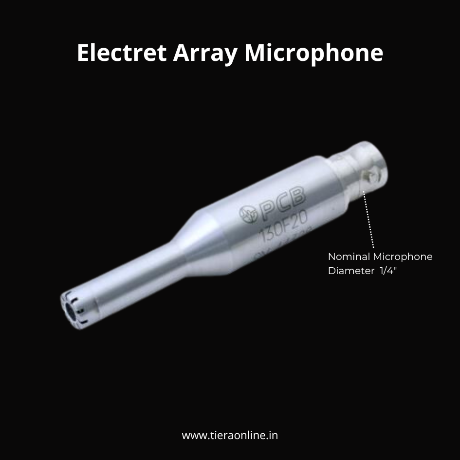
130F20 ICP® Electret Array Microphone
Matched ICP microphones are what make the phase-sensitive two-mic decomposition trustworthy.
- Diameter
- 1/4 inch
- Sensitivity
- 45 mV/Pa
PhonoVibe Series — Sound & Vibration DAQ
The transfer function is only as good as the two channels measuring it — matched, simultaneously sampled inputs.
- Sampling
- Simultaneous, 24-bit
From the TIERA store
The kit for this job
What we would actually put in front of someone doing the measurement this post describes — not the whole catalogue.
- T-Sonus Impedance TubeTIERA's impedance tube kit for acoustic material characterization. Combines 16 mm, 30 mm and 100 mm tube options, precision microphones, PhonoVibe DAQ, signal generation and TSONUS software to measure absorption coefficient and sound transmission loss.Request priceView →
- 130F20 ICP® Electret Array MicrophoneICP® Array Microphone with integral preamplifier, BNC jack connector, TEDS Nominal Microphone Diameter: 1/4″ Sensitivity: 45 mV/Pa Inherent Noise: 29 dB re 20 µPa₹57,600View →
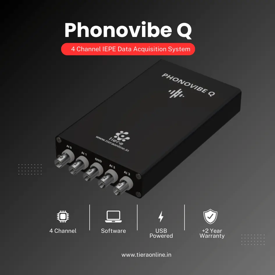 4 Channel IEPE Data Acquisition System – Phonovibe QFour Channels Standard plug & play USB Powered Take data from accelerometers, microphones, hammers, or any other IEPE Sensors T- VIB Software to acquire time waveforms, frequency spectra, overall vibration levels, FRF’s and octave measurements ** Windows 10 or above Operating System ** T-VIB Software base version comes with Time and Spectrum with Post processor TSAP 201. Check out TVIB Software regarding more module options.₹2,88,000View →
Use cases
Where this shows up in the field
An absorption number you can iterate against.
T-Sonus is built for the development loop — try a thickness, try an air gap, try a different density, and see the answer in seconds rather than booking a reverberation room.
We will tell you plainly which questions the tube answers and which it does not, because a mismatch there wastes far more money than the instrument costs.
- T-Sonus impedance tube — ISO 10534-2 two-microphone method
- Matched ICP microphones and simultaneous-sampling DAQ
- Guidance on tube diameter and spacing for your actual frequency range
Where this sits on the TIERA learning ladder.
The theory behind this article is covered free, in full, by the TIERA 101 primers: Acoustics & Noise 101, Measurement Setup 101. They are self-paced, interactive, and end in an exam and a certificate.
The primer covers what absorption is and how it is measured. Choosing between normal-incidence and random-incidence methods for a specific engineering decision — and knowing when neither is the right tool — is the applied material.
TIERA 101 is a free introductory primer, not an accredited ISO certification, and its hours do not count towards the formal training ISO 18436 requires.