Why a Failing Bearing Hides in the Noise — and How Envelope Demodulation Finds It
An early bearing defect is a tiny, perfectly repetitive impact buried under shaft and blade energy. Enveloping — band-pass around the resonance, then demodulate — makes its comb visible long before the machine gets loud.
The stone in your shoe
- Every rolling-element pass over a spall produces one brief micro-impact, then another at precisely the same interval, thousands of times an hour.
- Each impact carries very little energy next to the shaft, the blades and the mesh — so the defect is never the biggest thing in the signal.
- The information is not in the size of the signal. It is in the rhythm.
Walk with a small stone caught in your shoe and you feel the same little knock at the same point of every stride. It is not loud. It does not change your walking rhythm. But it is perfectly regular, and that regularity is what tells you something is trapped in there. An early bearing defect behaves exactly like that stone: every time a rolling element passes over a small spall, it produces one brief, sharp micro-impact — and then another, at precisely the same interval, thousands of times an hour.
Each impact carries very little energy compared with everything else the machine is doing. The shaft is turning, blades are passing, gears are meshing, and all of that produces smooth, large vibration that dwarfs the defect. The information is not in the size of the signal. It is in the rhythm.
Why the raw spectrum hides it
- A short, sharp impact spreads its small energy across a huge range of frequencies, so no single spectral line collects much of it.
- The machine's steady components do the opposite — 1×, blade pass and gear mesh each pile large energy into one tall line.
- The fault frequency is there in principle and at or below the floor in practice, which is why spectrum-only routines meet bearings late and audible.
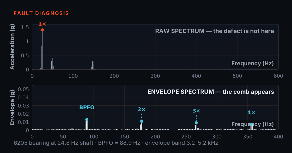
Take an ordinary FFT of that signal and the impacts almost vanish. A short, sharp impact spreads its small energy across a huge range of frequencies, so no single spectral line gets much of it. Meanwhile the machine's steady components — 1× running speed and its harmonics, blade pass, gear mesh — each concentrate their large energy into one tall line. The result is a spectrum dominated by lines you already expected, with the defect's contribution sitting at or below the floor between them.
This is why bearings so often reach a late, audible stage before a spectrum-only routine catches them. The fault frequency may be there in principle, but at an early stage it is simply too small to distinguish from noise in a plot scaled to show shaft and blade energy.
Four frequencies, four surfaces
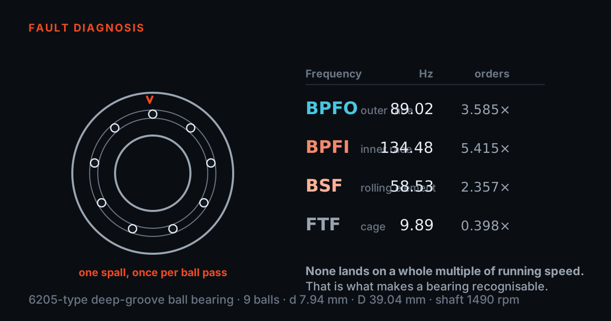
A rolling-element bearing has four moving surfaces, and each produces its own repetition rate when damaged. BPFO, the ball pass frequency of the outer race, is how often rolling elements pass a fixed point on the outer ring — a spall there gets struck at exactly that rate. BPFI is the same idea for the inner race, which turns with the shaft, so its impacts are usually modulated by running speed. BSF, the ball spin frequency, is how fast each rolling element spins on its own axis — a damaged ball strikes both races on each rotation, which is why ball damage usually shows up at 2×BSF rather than BSF itself. FTF, the fundamental train frequency, is the rotation rate of the cage that spaces the rolling elements, always slower than the shaft.
These four rates are set by geometry: the number of rolling elements, their diameter, the pitch diameter, and the contact angle, all scaled by shaft speed. None of them lands on a clean multiple of running speed, which is precisely what makes them recognisable — a peak at 3.08 orders is a bearing talking, not the shaft.
Enveloping: tune past the noise, then listen to the rhythm
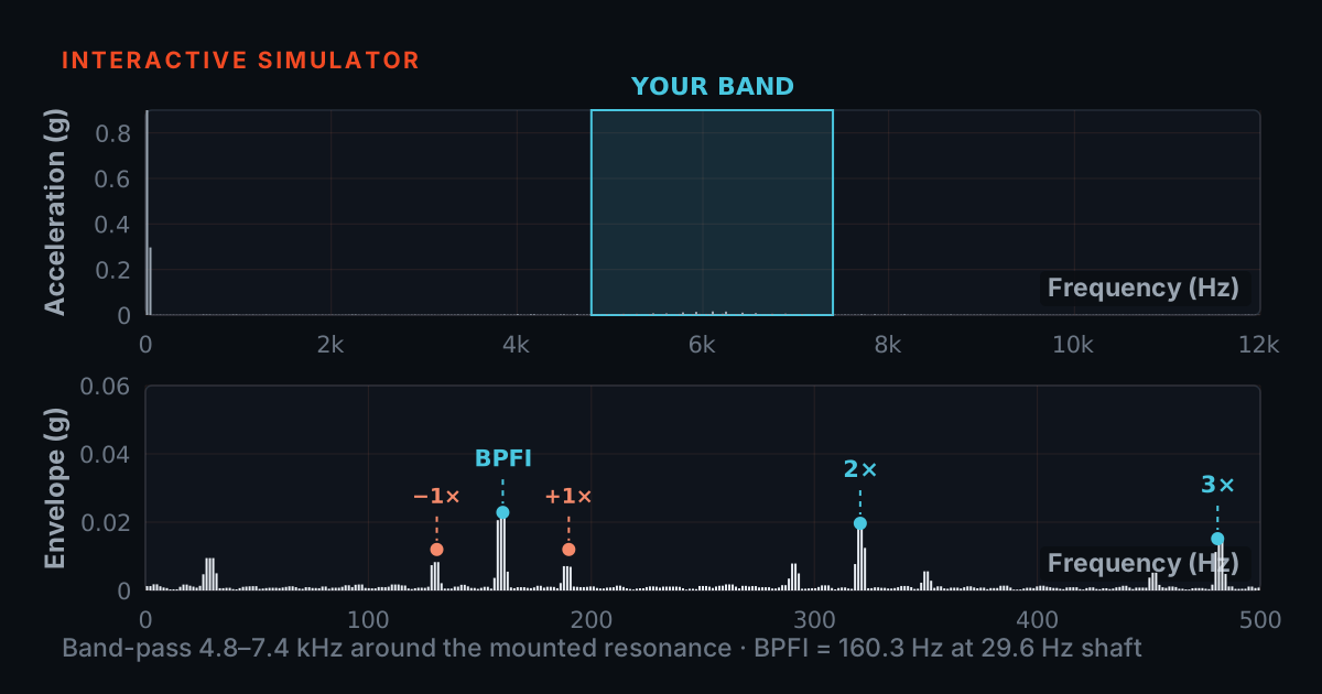
Envelope demodulation works because each micro-impact does one useful thing: it rings the bearing housing at its structural resonance, typically well up in the kilohertz range — far above where shaft, blade, and mesh energy live. So instead of looking for the fault frequency directly, you band-pass filter around that quiet resonance region, keeping only the bursts of ringing. Then you demodulate: rectify and smooth the filtered signal so that what remains is the outline — the envelope — of the bursts. An FFT of that envelope reveals how often the bursts occur, which is the fault frequency itself.
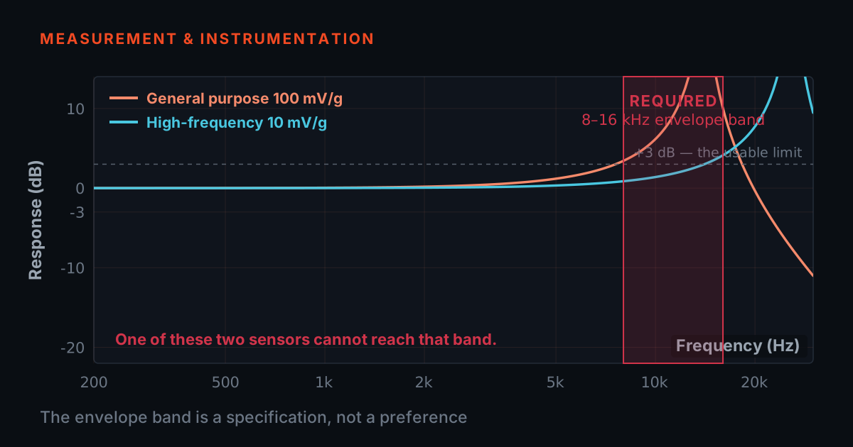
This is where the capture chain earns its keep. The resonance bursts are high-frequency and small, so you need bandwidth and dynamic range to record them at all: PhonoVibe Q, O, and HD sample at 128 kHz with 24-bit resolution across a 0.5 Hz to 60 kHz bandwidth, with IEPE sensor power built in. Mounting matters just as much at these frequencies — a stud or adhesive-mounted accelerometer preserves the high-frequency path far better than a loose fixture, which is why the TIERA accessory range runs from SS304 triaxial mounting blocks for permanent points to magnetic mounts for walk-around routes, with low-noise cabling to keep triboelectric hash out of a signal this small.
The comb that gives it away
- Even spacing is the signature. Random impacts from turbulence or looseness raise the floor; they do not build a comb.
- Match the spacing to BPFO, BPFI, 2×BSF or FTF for that bearing at that speed and you have named the bearing and the surface.
- Sidebands at running speed around a BPFI comb say the damaged inner race is moving in and out of the load zone once per revolution.
The FFT of the envelope is where the diagnosis happens. A repetitive impact train produces a comb: a line at the fault frequency and a family of evenly spaced harmonics marching up the axis, all separated by exactly the same interval. Even spacing is the signature — random impacts from turbulence or looseness raise the floor, but they do not build a comb. If the spacing matches BPFO for that bearing at that shaft speed, you know which bearing and which surface, months before the raw spectrum shows anything.
Sidebands refine the story further. A comb spaced at BPFI and flanked by sidebands at running speed says the damaged inner race is moving in and out of the load zone once per revolution. Reading this takes cursors more than mathematics: in TVIB's TSAP201 analyser, band-pass filtering, FFT sizes up to 102,400 points, and harmonic and sideband cursors let you lay a ruler over the comb and check the spacing directly, and recorded signals can be re-processed after the fact as the picture develops.
A representative case — and how to practise it
A representative case, not a specific customer: a process fan runs a routine monthly measurement. The velocity spectrum is unremarkable — a modest 1×, blade pass where it belongs, nothing trending. An envelope reading on the drive-end bearing housing, however, shows a small but clean comb whose spacing matches the outer-race frequency for that bearing at that speed. Nothing is loud yet, so the finding goes on the watch list; over following readings the comb harmonics grow and sidebands appear. The bearing is replaced during a planned stop, and the removed race shows a spall in the load zone right where the comb said it would be. The point of the example is the sequence: the envelope gave the early warning while the raw spectrum was still reassuring.
The technique rewards practice on faults you can trust. A TMFSS simulator with seeded bearing defects — outer race, inner race, cage, and rolling element — lets an analyst capture each one under controlled speed and see the corresponding comb move, which builds the pattern recognition that field data alone develops slowly. For the theory behind these figures, the free Bearing & Gear Analysis 101 primer at 101.tieraonline.in walks through it step by step — a free primer, not an accredited ISO certification. When you want the formal credential, TIERA's TCAT programme runs Cat I through Cat IV analyst training (see /services), with proctored examinations conducted at exams.tieraonline.in.
TIERA instruments that do this work.

PhonoVibe Series — Sound & Vibration DAQ
Enveloping feeds on the kilohertz-range resonance ringing — the Q/O/HD's 128 kHz sampling and 0.5 Hz – 60 kHz bandwidth reach that band with headroom to spare.
- ADC resolution
- 24-bit
- Sampling (Q/O/HD)
- 128 kHz
- Bandwidth (Q/O/HD)
- 0.5 Hz – 60 kHz
- Sensor power
- 24 V, 4 mA (IEPE/ICP/CCLD)
- Sampling mode
- Simultaneous on every input

TVIB — Sound & Vibration Analysis Software
The rest of the envelope chain: FIR/IIR band-pass around the resonance, then harmonic and sideband cursors to lay a ruler over the defect comb.
- Filters
- FIR and IIR
- FFT size
- Up to 102,400 points
- Cursors
- Harmonic / band / sideband
- Base module
- TSAP201 — free with PhonoVibe

Sensors & Accessories
The fixture decides whether the resonance band survives: for this job use the SS304 stud-mount block or adhesive pads, not a magnet mount — a loose magnetic coupling attenuates exactly the high frequencies enveloping needs.
- Mounting block
- TMB-101-1-A SS304 triaxial
- Adhesive pads
- TAP-101-1A set, non-magnetic surfaces
- Cable
- CA-101-5-M-B low-noise coaxial, 5 m
- Accelerometer
- 151A500D — 500 mV/g industrial
From the TIERA store
The kit for this job
What we would actually put in front of someone doing the measurement this post describes — not the whole catalogue.
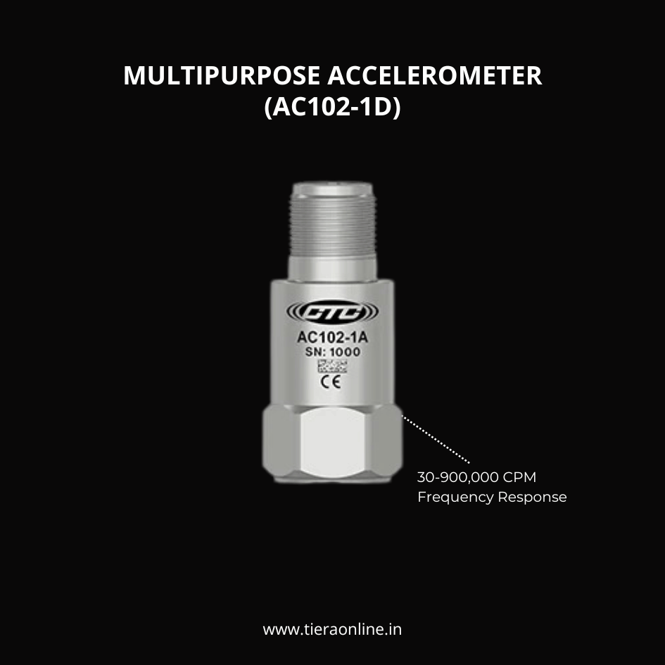 AC102-1D, MULTIPURPOSE ACCELEROMETERMULTIPURPOSE ACCELEROMETER, TOP EXIT 2 PIN CONNECTOR, 100 MV/G, ±10% 30-900,000 CPM Frequency Response (±3dB) -58 to 250 °F (-50 to 121 °C) Temperature Range Welded, Hermetic Sealing CTC’s Best Selling, Multi-Purpose Sensor Ideally Suited for Thousands of Applications₹14,750View →
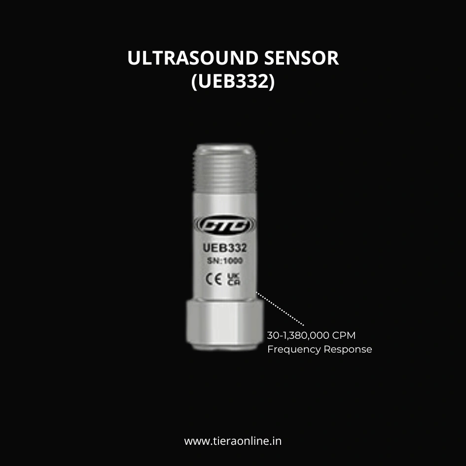 UEB332, ULTRASOUND SENSORCTC’s High Frequency Ultrasound Accelerometer. High Amplitude Resonance Peak for Stress Wave Measurement Techniques. It works on the IEPE Amplifier Technology.₹44,560View →
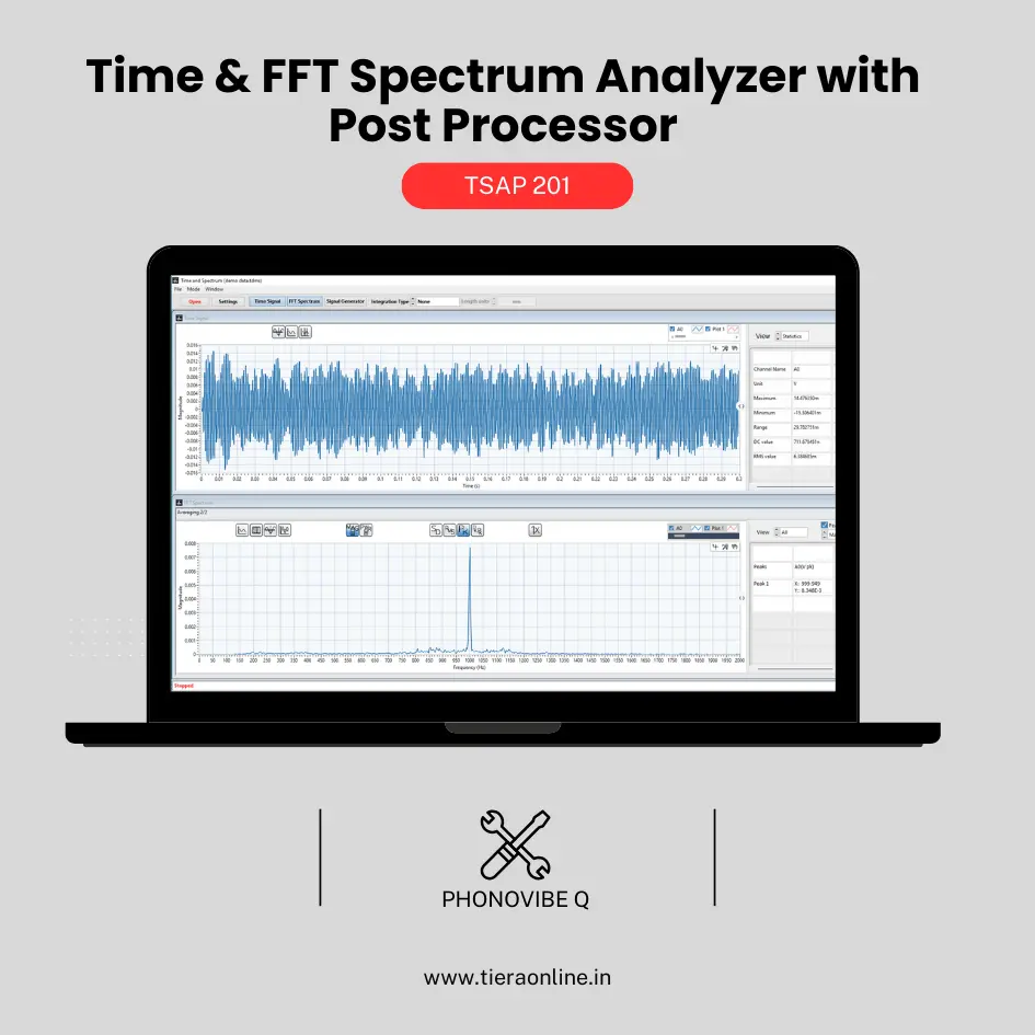 TSAP 201 -Time & FFT Spectrum Analyzer with Post Processor (Phonovibe Q)Use Cases Bump Test Product Development Off route Machine Vibration analysis. Drop Test Product Development & Research₹34,560View →
Use cases
Where this shows up in the field
Catch the bearing fault while the spectrum still looks fine
Everything in this post depends on reaching the resonance band, and that is a hardware question before it is a software one. PhonoVibe Q, O and HD sample at 128 kHz with 24-bit resolution across a 0.5 Hz – 60 kHz bandwidth, with IEPE sensor power built in — enough headroom to record the kilohertz-range ringing that envelope analysis feeds on. Every PhonoVibe ships with TVIB TSAP201, which supplies the rest of the chain: FIR and IIR band-pass filtering, FFT up to 102,400 points, and the harmonic, band and sideband cursors that let you lay a ruler over the comb. Recorded signals can be re-processed later as the picture develops.
The quiet failure mode is the fixture: a loose mount attenuates exactly the high frequencies that carry the diagnosis. For permanent measurement points our accessory range includes SS304 triaxial mounting blocks and adhesive pads for non-magnetic surfaces, with low-noise coaxial cabling to keep triboelectric hash out of a signal this small. And if you want the pattern recognition before the plant provides real failures, the TMFSS simulator seeds outer-race, inner-race, cage and rolling-element defects under controlled speed, so each comb in this post is one you have already measured yourself.
- PhonoVibe Q / O / HD: 24-bit, 128 kHz sampling, 0.5 Hz – 60 kHz bandwidth, IEPE sensor power on every channel
- TVIB TSAP201 (included with every PhonoVibe): band-pass filters, up to 102,400-point FFT, harmonic and sideband cursors, signal recording and post-processing
- Mounting and cabling that protect the high-frequency path: SS304 triaxial blocks, adhesive pad sets, low-noise coaxial cables
- TMFSS benchtop simulator with seeded bearing faults — outer race, inner race, cage, rolling element — for controlled practice
Where this sits on the TIERA learning ladder.
The theory behind this article is covered free, in full, by the TIERA 101 primers: Bearing & Gear Analysis 101. They are self-paced, interactive, and end in an exam and a certificate.
TCAT Cat I-IV adds structured analyst training with proctored examinations at exams.tieraonline.in — the free 101 primers cover the theory, TCAT certifies you can apply it.
TIERA 101 is a free introductory primer, not an accredited ISO certification, and its hours do not count towards the formal training ISO 18436 requires.